Radiation shield

a radiation shield and shield technology, applied in the field of radiation shields, can solve the problems of difficult to see the patient, large exposure, and radiation can be redirected or scattered lik

Inactive Publication Date: 2007-02-08
TREUTH MARK G
View PDF2 Cites 31 Cited by
  • Summary
  • Abstract
  • Description
  • Claims
  • Application Information

AI Technical Summary

Benefits of technology

[0004] An object of this invention is to provide a radiation shield which blocks scattere

Problems solved by technology

The drawback with this arrangement is that the radiation can be redirected or scattered like a bullet that ricochets.
Over the years, however, the exposure is great.
The drawback with these methods, however, is that it is difficult to see the patient.
In addition, because the

Method used


Image

  • Radiation shield
  • Radiation shield

Examples


Embodiment Construction

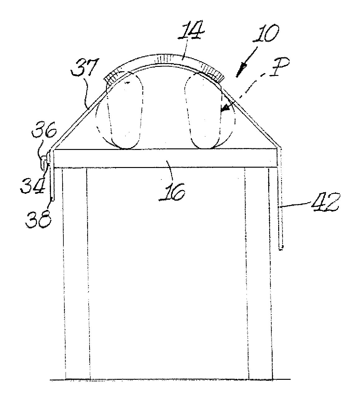
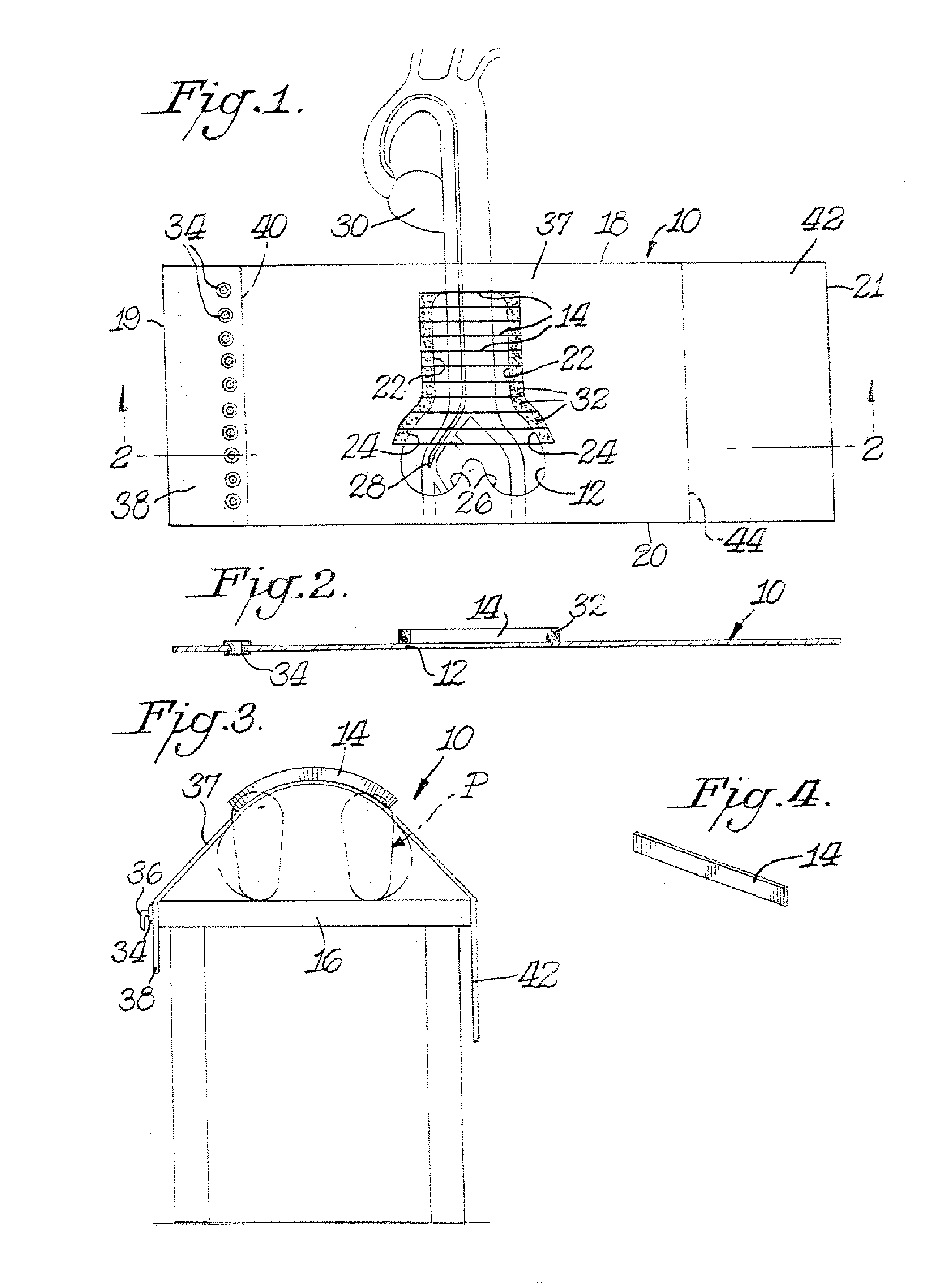
[0012] In a preferred practice of the invention, such as illustrated in FIGS. 1-4, the radiation shield comprises a radio-opaque drape 10 made of any suitable radiation-opaque material, such as lead. The drape 10 includes a cut-out 12 having radiation control structure located in a portion of the open area 12 to minimize exposure to scattered radiation. Preferably, the radiation control structure is in the form of a vent having a plurality of radio-opaque slats 14 extending at least partially across at least a portion of the open area 12. Cut-out or open area 12 is located, for example, at about the center of the drape 10 so that it is properly disposed at the patient when the patient is lying on a table 16 as shown in FIG. 3.

[0013] In the specifically illustrated practice of this invention the radiation shield is intended to function in connection with cardiac imaging where it is desired to view catheters as they pass through the aorta. In order to minimize the size of the open ar...


PUM


Abstract

A radiation shield includes a radio-opaque drape which has an open area extending completely through the drape to provide a viewing site. Radiation control structure in the form of a vent system is located in the open area. The vent system includes a plurality of radio-opaque slats extending at least partially across at least a portion of the open area. The slats preferably extend outwardly away from the surface of the drape to facilitate the capturing of scattered radiation.

Description

CROSS-REFERENCE TO RELATED APPLICATION [0001] This application is based on provisional application Ser. No. 60 / 705,860 filed Aug. 5, 2005.BACKGROUND OF THE INVENTION [0002] Cardiac imaging uses an x-ray source under the patient that emits x-rays which travel through the x-ray table and the patient to above the table imager. In such procedures x-rays are used, for example, during a cardiac cathertization procedure to image the coronary arteries. The drawback with this arrangement is that the radiation can be redirected or scattered like a bullet that ricochets. While the patient is rarely exposed to radiation, the cath lab personnel are exposed to radiation from the scattered radiation. For one procedure the scattering does not result in a lot of exposure. Over the years, however, the exposure is great. [0003] Current methods include shields that move in front of the cath lab personnel. The drawback with these methods, however, is that it is difficult to see the patient. In addition,...

Claims


Application Information

Patent Timeline
IPC IPC(8): G21F3/02
CPCA61B6/107G21F3/02G21Y2002/201G21Y2004/303G21Y2002/501G21Y2004/30G21Y2002/304
Inventor TREUTH, MARK G.
Owner TREUTH MARK G
Why Eureka
Try Eureka