Autonomous microfluidic device for sample preparation

Active Publication Date: 2022-03-17
INTELLIGENT VIRUS IMAGING
View PDF0 Cites 0 Cited by
  • Summary
  • Abstract
  • Description
  • Claims
  • Application Information

AI Technical Summary

Benefits of technology

[0014]As indicated above, some automatic or semi-automated preparation methods have been suggested in the past. They rely on robotic dispensers, microfluidics using special equipment or special sample holders connected to a pipetting device. The robotic dispensers require only minute sample volume but instead rely on highly specialized equipment. The microfluidic-based sample preparation approach results in more consistent preparations but again rely on special equipment (special grid holder and external pressure pump) and require about 10-times larger sample volumes compared to manual preparation. A method using a special pipette tip with a pocket/slit holding the grid has also been suggested. This mprep-based approach also requires larger sample volumes and involves manual timing steps. In addition, the liquids are flushed on both sides of the grid that increase the risk for poor quality preparations.
[0015]Hence, there is a need for a more reliable and consistent nsTEM sample preparation method. T

Problems solved by technology

One problem is that this manual procedure is highly dependent on the skill of the operator which affects the preparation consistency and leads to unreliable results.
Inconsistent timing of the manual steps and the final blotting are often the cause for bad TEM grid preparations.
However, they require special instrumentation and are significantly more complex and time-consuming than the manual preparation protocol.
It also requires special equipment and involves the user to control the timing of every preparation step which makes the preparation method unreliable and inconsistent.
As indicated above, the expert task of preparing the sample for

Method used


Image

  • Autonomous microfluidic device for sample preparation
  • Autonomous microfluidic device for sample preparation
  • Autonomous microfluidic device for sample preparation

Examples


Example

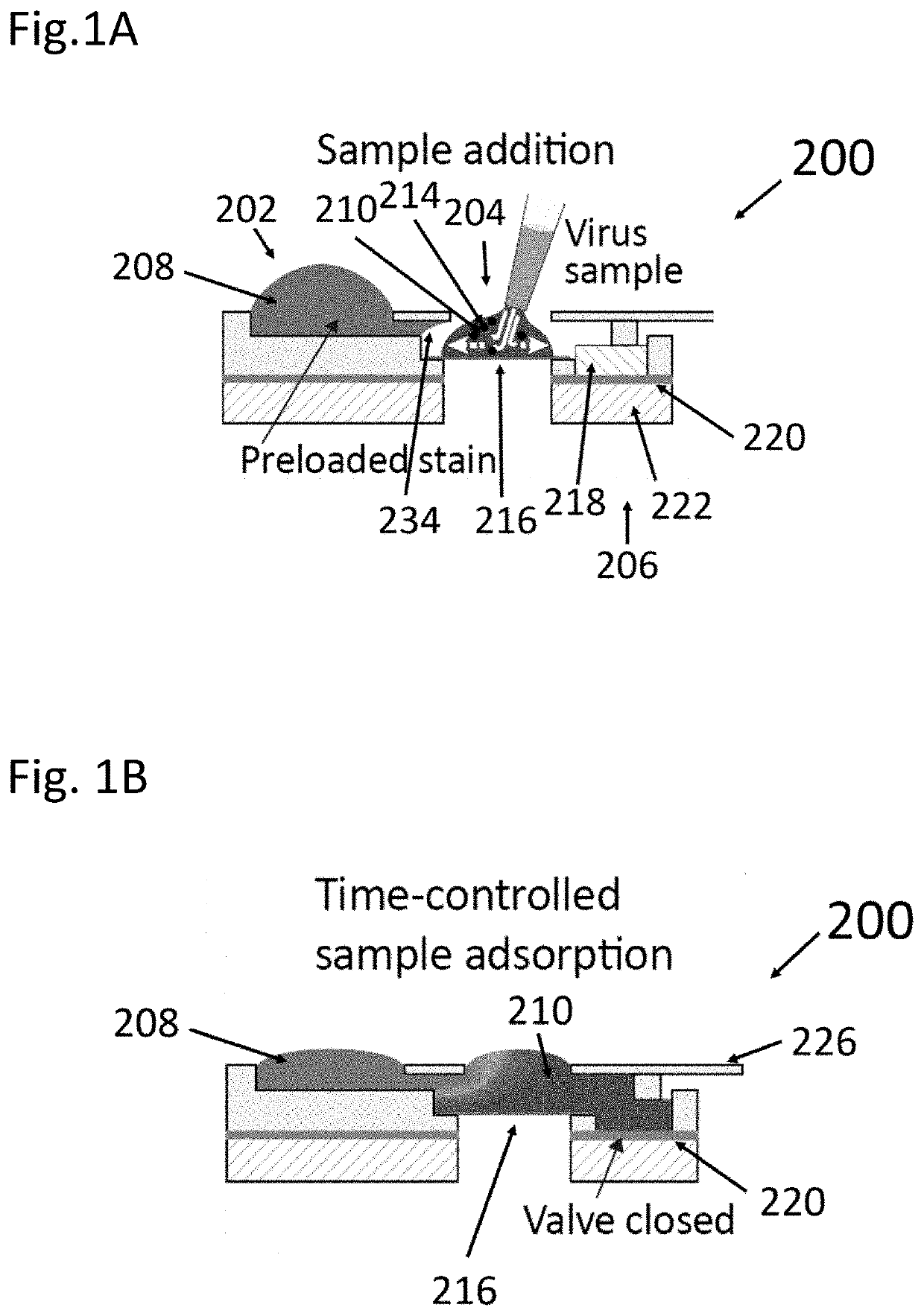
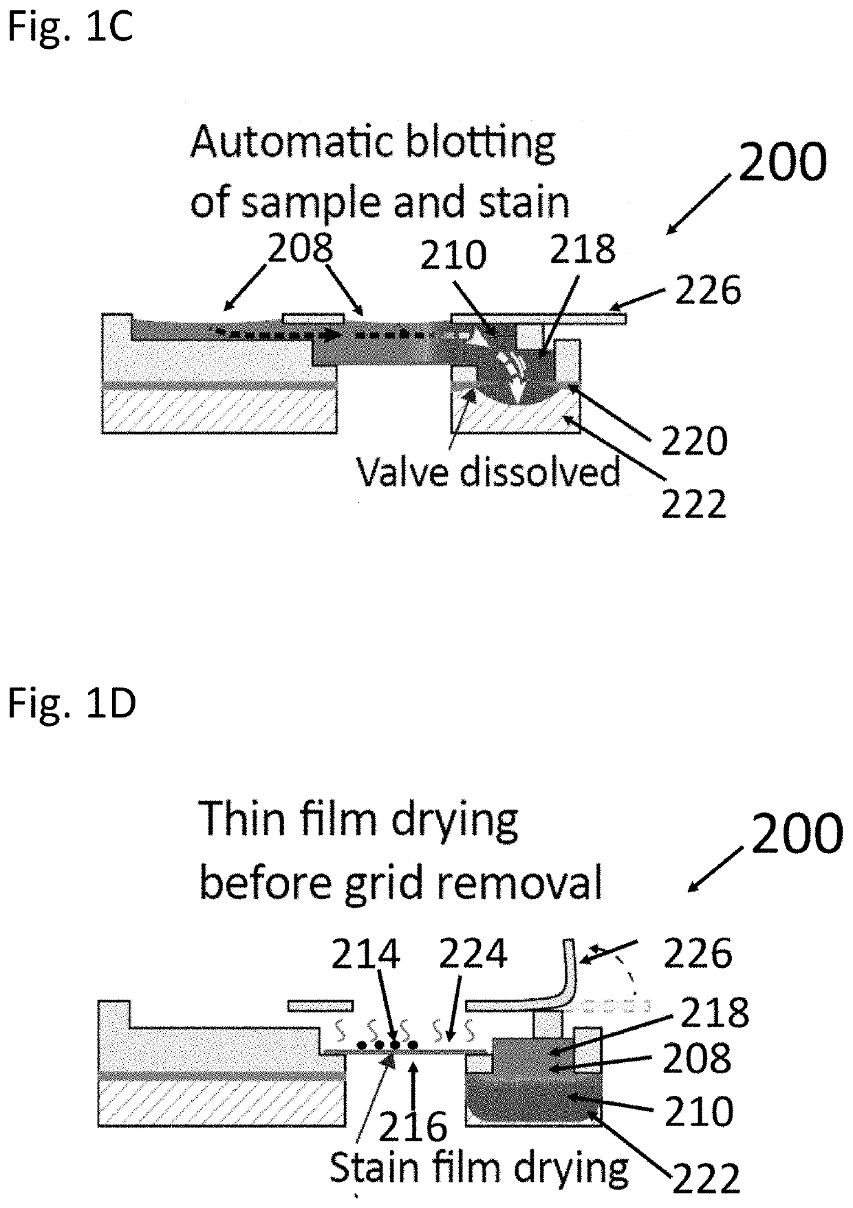
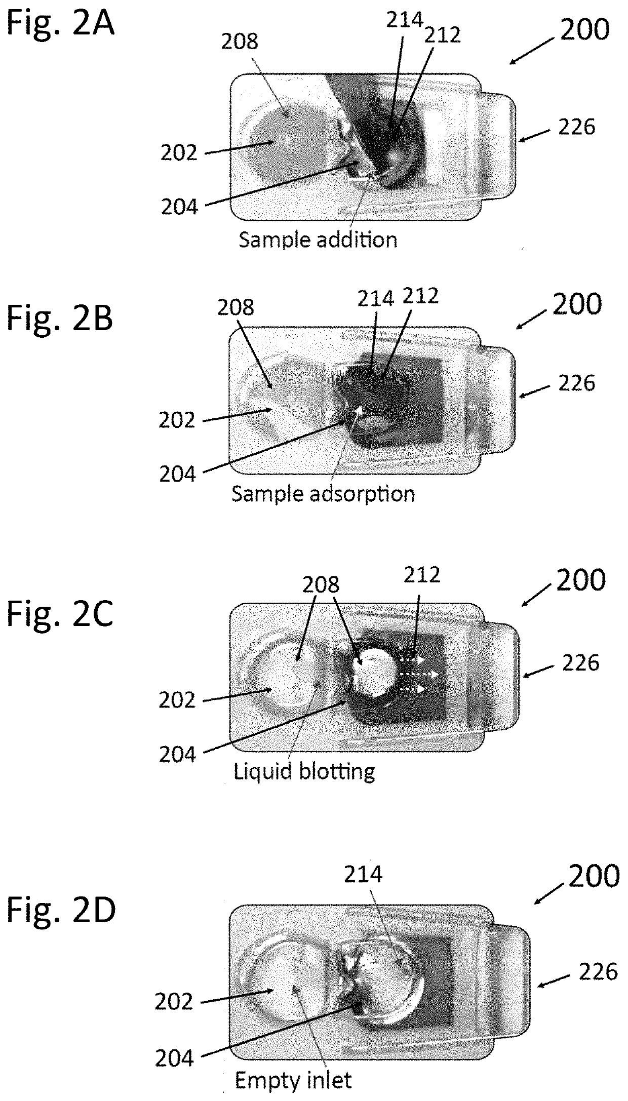
[0092]A capillary-driven microfluidic device of the present invention is presented herein for sample preparation that requires the same small liquid volumes as the conventional manual procedure does, and which requires minimal user-interaction. More particularly, the sample support is preferably a grid, such as a TEM grid. The user merely initiates the autonomous sample preparation process, waits for about one minute and then extracts the TEM grid that is ready for imaging in a TEM or SEM microscope. The autonomous process of the present invention typically requires a film, that is soluble by the sample liquid, such as a PVA (polyvinyl alcohol) film for a water-based sample liquid, that automatically controls the time for sample adsorption and draining of excess liquids. Microfluidic consistency for five microfluidic devices is demonstrated below by comparing the timing and duration of the microfluidic TEM grid preparation events. Furthermore, the adjustability of the time-delay is ...


PUM


Abstract

The method is for preparing a sample in a microfluidic device. A microfluidic device is provided that has a first reservoir in fluid communication with a second reservoir in fluid communication with and adjacent to a draining unit that has a first absorbing member disposed therein. The first reservoir contains a first liquid that is held in the first reservoir by a capillary stop valve connecting the first and second reservoirs. The second reservoir has a sample support disposed therein. A second liquid, containing substances, is added to the second reservoir. The second liquid contacts the first liquid and the first absorbing member. The first absorbing member absorbs the second liquid and the first liquid. The substances adhere to the sample support.

Description

PRIOR APPLICATION[0001]This is a continuation-in-part (CIP) patent application that claims priority from U.S. patent application Ser. No. 17 / 023,922, filed 17 Sep. 2020.TECHNICAL FIELD[0002]The present invention generally relates to a device and method for consistent and user-independent preparation of particulate or elongate fiber-like samples, such as micro-particles, nanoparticles and / or micro / nano-sized fibers, for subsequent analysis using microscopy or other inspection techniques. In particular this is useful for applications in transmission electron microscopy (TEM) or scanning electron microscopy (SEM).BACKGROUND AND SUMMARY OF THE INVENTION[0003]A consistent, user-independent and repeatable sample preparation method is necessary for objective analysis of liquid samples of micro and nano-sized particles such as virus particles, virus-like particles, proteins, protein complexes, fibers, delivery vesicles, pharmaceuticals and inorganic particles.[0004]For example, modified vir...

Claims


Application Information

Patent Timeline
IPC IPC(8): C12M3/06B01L3/00
CPCC12M23/16B01L2400/0688B01L2300/0864B01L3/502738B01L2300/069B01L2400/0677B01L3/5023B01L2200/16
Inventor HAUSER, JANOSCHKYLBERG, GUSTAFSTEMME, GÖRANSINTORN, IDA-MARIAROXHED, NICLAS
Owner INTELLIGENT VIRUS IMAGING
Why Eureka
Try Eureka