

Toe sock
- Summary
- Abstract
- Description
- Claims
- Application Information
AI Technical Summary
Benefits of technology
Problems solved by technology
Method used
Image

Examples
Embodiment Construction
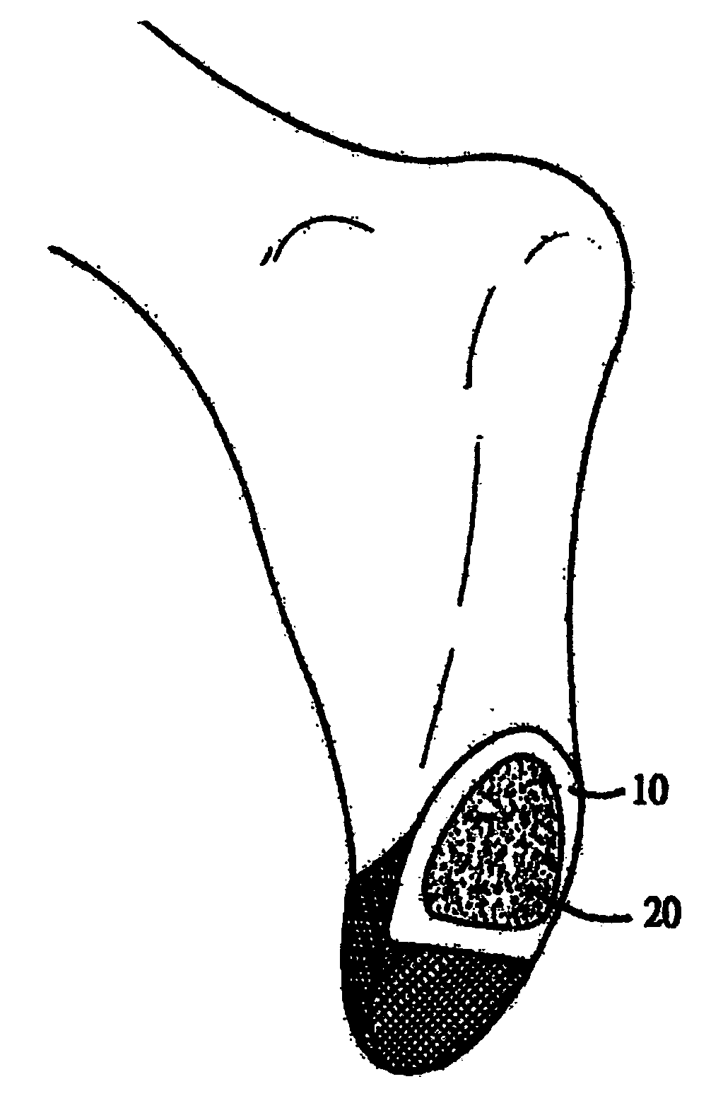
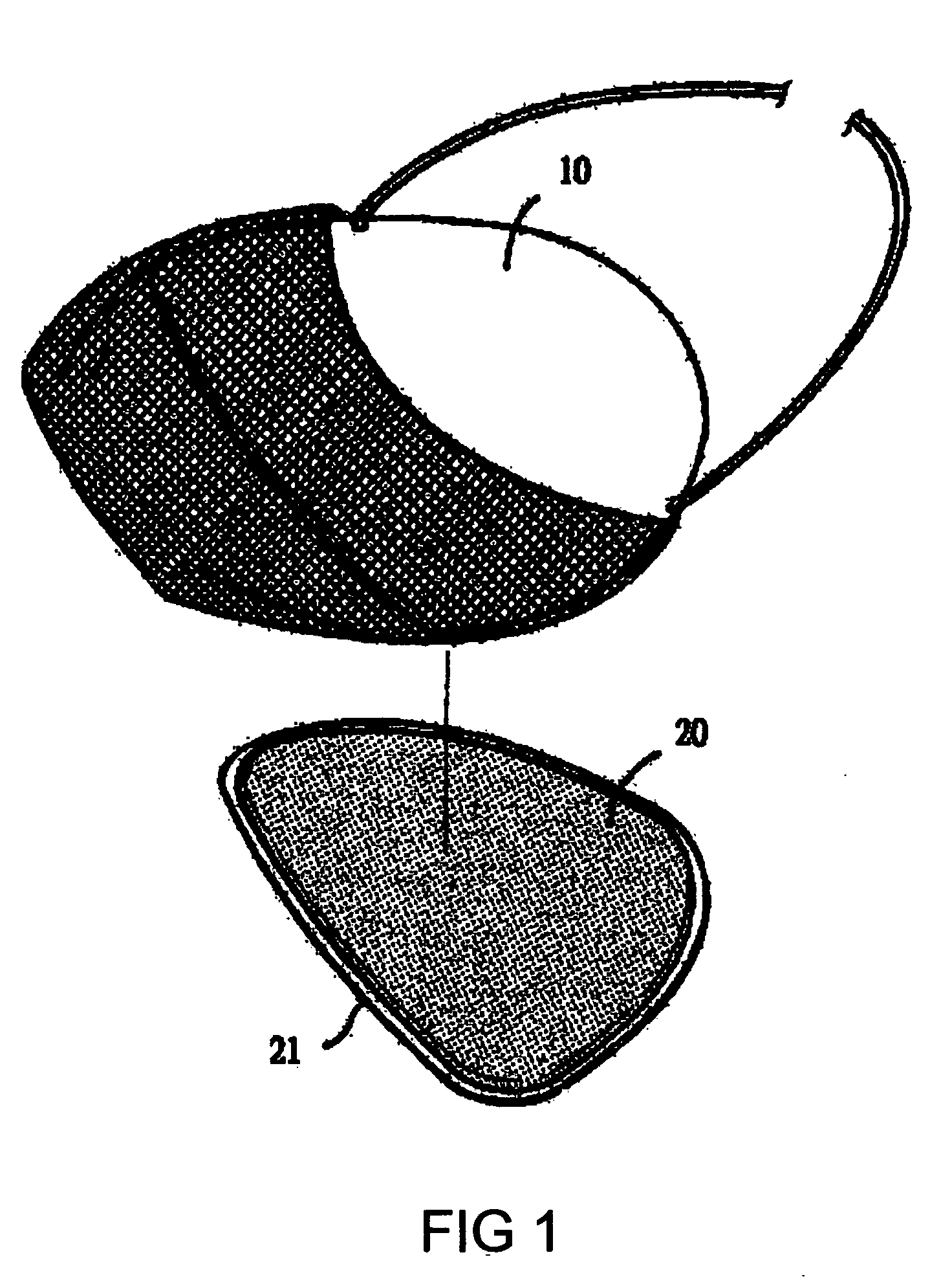
[0019] Referring to FIG. 1, a toe sock according to the present invention comprises a pad member 10 and a slip proof elastic rubber 20.
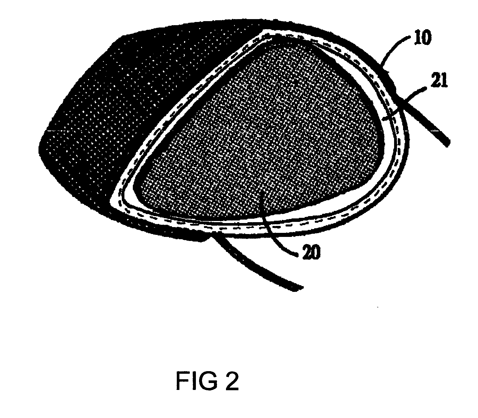
[0020] Referring to FIGS. 2 and 3 in company with FIG. 1, the pad member 10 is made of sewed cloth to provide an intermediate layer for being inserted with soft material such as sponge or foam material. The pad member 10 is provided with a shape almost the same as the front part of a foot of a human body including the toe part so as to fit with the front part of a foot. In addition, other shapes such as the pad member 10A shown in FIG. 4 suitable for foot wearing sandal or slipper, the pad member 10B shown in FIG. 5 suitable for correcting turned up thumb toe, the pad member 10C shown in FIG. 6 suitable for wearing leather shoe or high heel shoe and the pad member 10D shown in FIG. 7 fitting with the thumb toe and the little toe and being laid under front foot palm.
[0021] Referring to FIGS. 1, 2 and 3 again, the anti-slip rubber layer 20 is soft, s...
PUM
 Abstract
Description
Claims
Application Information