Prosthetic knee joint structure

a knee joint and prosthetic technology, applied in the field of prosthetic legs, can solve the problems of inability to keep the bending of the prosthetic leg within a range of the elements of the conventional prosthetic knee joint, and the most important and complicated part of the prosthetic leg is the knee join

Active Publication Date: 2006-05-04
CHENG CHIA PAO
View PDF4 Cites 1 Cited by
  • Summary
  • Abstract
  • Description
  • Claims
  • Application Information

AI Technical Summary

Benefits of technology

[0009] A major objective of the present invention is that, when the user is walking or standing, the bending of the prosthetic leg is confined within a range so that the shin wouldn't dangle, and the prosthetic leg is able to absorb shocks even when the prosthetic is bended within the specific range.
[0010] To achieve the foregoing objective, the prosthetic knee joint according to the present invention contains an upper member for connecting to a prosthetic thigh, a lower member for connecting to prosthetic shin and foot, a linking device for connecting the upper and lower members which mainly includes a joining element and connecting rods, a cushion element, and a resilient device mainly including a supporting element, a first cap element, a first helical spring, a first adjustment screw, a second cap element, a second helical spring, a second adjustment screw, and a stopping plate. The resilient device, by the force exerted from the helical springs, confines the bending of the prosthetic knee joint within a specific range. The cushion element, on the other hand, is able to absorb the shock as long as the prosthetic knee joint is bended within the specific range.

Problems solved by technology

The most important and complicated part of a prosthetic leg is the knee joint.
The drawbacks of these conventional prosthetic knee joints are as follows.
However, when the user is walking downhill, the prosthetic leg is bended with a small angle and the cushion pad is therefore unable to absorb the shock.
In addition, the joining elements of the conventional prosthetic knee joint are unable to keep the bending of the prosthetic leg within a range.
Therefore, when the user is walking on flat ground or on a slope, the shin would dangle from the knee joint when the prosthetic leg is lifted from the ground, causing the user to suddenly kneel down.

Method used


Image

  • Prosthetic knee joint structure
  • Prosthetic knee joint structure
  • Prosthetic knee joint structure

Examples


Embodiment Construction

[0017] The following descriptions are of exemplary embodiments only, and are not intended to limit the scope, applicability or configuration of the invention in any way. Rather, the following description provides a convenient illustration for implementing exemplary embodiments of the invention. Various changes to the described embodiments may be made in the function and arrangement of the elements described without departing from the scope of the invention as set forth in the appended claims.

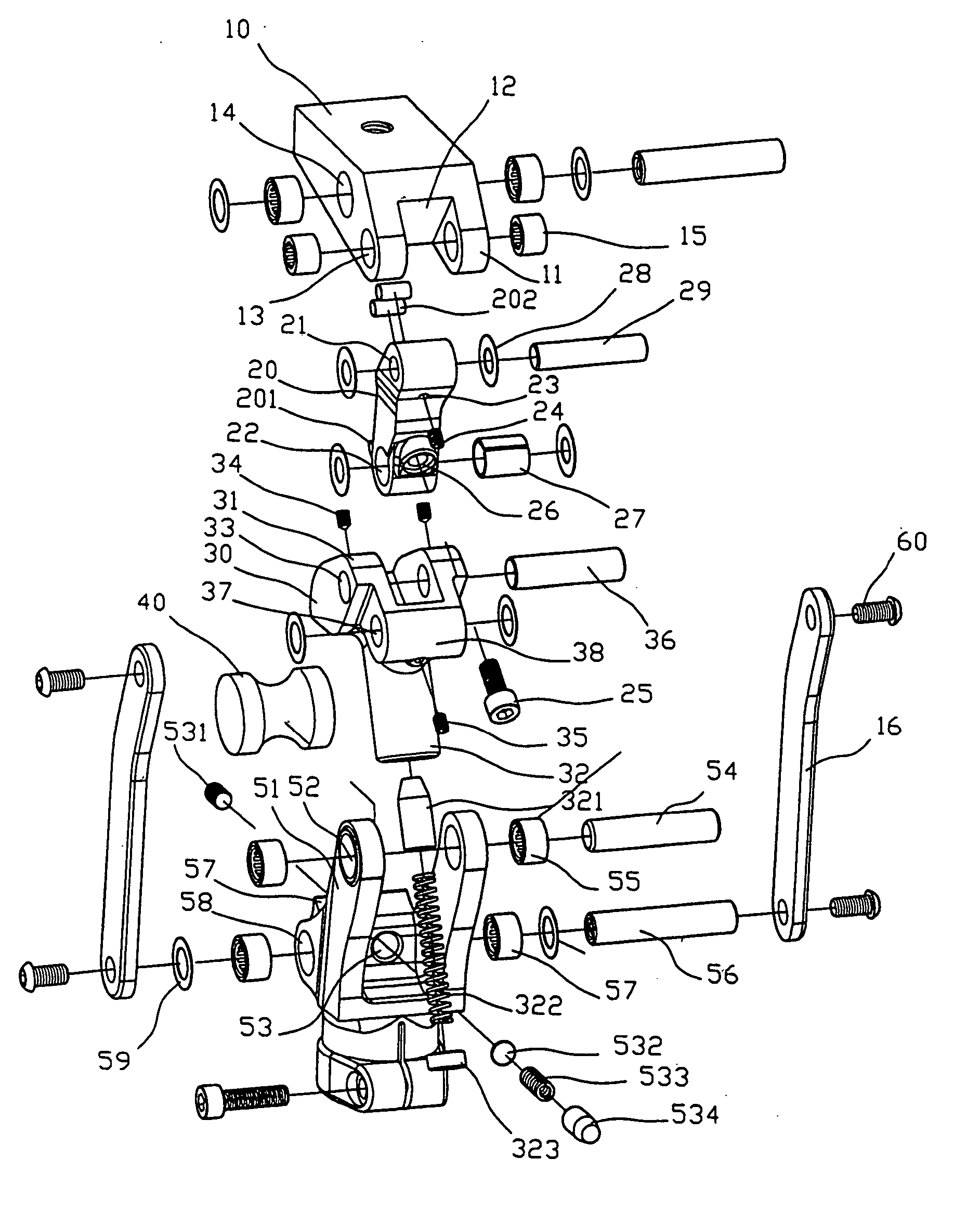
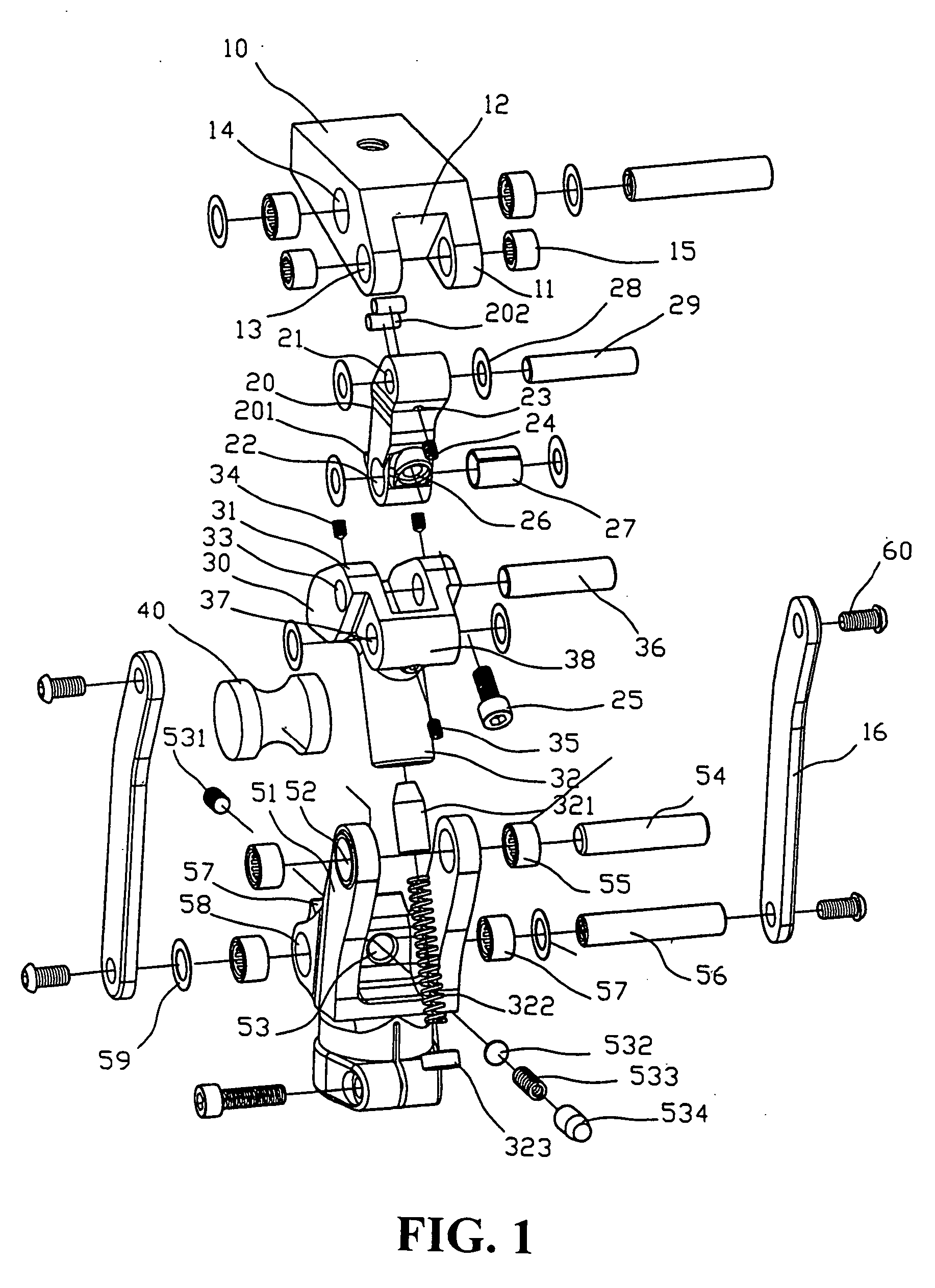
[0018] As illustrated in FIG. 1, an embodiment of the prosthetic knee joint according to the present invention contains an upper member 10 for connecting to a prosthetic thigh, a lower member 50 for connecting to prosthetic shin and foot, a lining device for connecting the upper and lower members 10 and 50 which mainly includes a joining element 20 and connecting rods 16, a cushion element 40, and a resilient device for shock absorption. The resilient device in turn mainly includes a supporting...


PUM


Abstract

A prosthetic knee joint structure is provided herein. The knee join mainly contains an upper member for connecting to a prosthetic thigh, a lower member for connecting to prosthetic shin and foot, a linking device for connecting the upper and lower members, a cushion element, and a resilient device. During walking, the resilient device prevents the shin from dangling and the knee joint from sudden bending and kneeling-down. The cushion element absorbs the shock when the prosthetic leg is walking on a flat ground or slope.

Description

CROSS-REFERENCE TO RELATED APPLICATIONS [0001] This is a continuation-in-part of U.S. application Ser. No. 10 / 625,660.BACKGROUND OF THE INVENTION [0002] (a) Technical Field of the Invention [0003] The present invention generally relates to prosthetic legs, and more particularly to a knee joint for prosthetic legs which confines the bending angle within a range and absorbs the shocks during walking. [0004] (b) Description of the Prior Art [0005] The most important and complicated part of a prosthetic leg is the knee joint. The prosthetic knee joint not only should work like a real human joint, but also should make the user walk in a natural way. [0006] Conventional prosthetic knee joints, as disclosed in R.O.C. Patent No. 549,074, utilize a plurality of joining elements to link a prosthetic thigh and prosthetic shin and foot. The prosthetic knee joint could imitate how a real human joint bends, and a cushion pad is configured on a lower joining element for absorbing the shock from th...

Claims


Application Information

Patent Timeline
Patent Type & Authority Applications(United States)
IPC IPC(8): A61F2/64A61F2/50A61F2/68
CPCA61F2/644A61F2/68A61F2002/503A61F2002/5073A61F2002/5075
Inventor CHENG, YAO-TENG
Owner CHENG CHIA PAO
Why Eureka
Try Eureka