Angle adjustor
a technology of angle adjustment and adjustor, which is applied in the direction of machine supports, instruments, other domestic objects, etc., can solve the problems of not being stably supported, complicating the manufacturing process of adjustors, and musical instruments, which have been adjusted to a desired angular position, etc., to achieve stable angle adjustment, simple structure, and easy manufacturing
- Summary
- Abstract
- Description
- Claims
- Application Information
AI Technical Summary
Benefits of technology
Problems solved by technology
Method used
Image
Examples
first embodiment
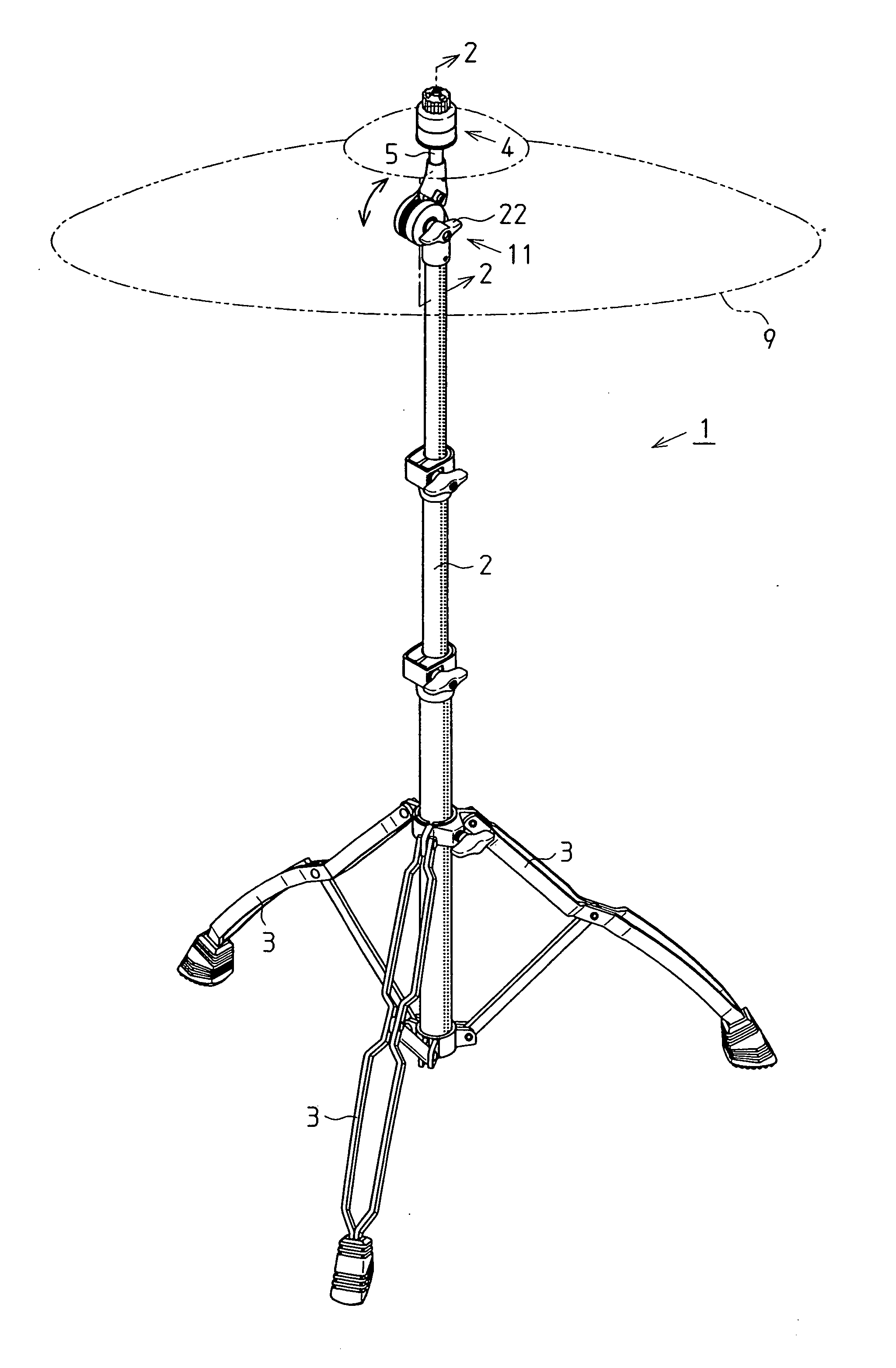
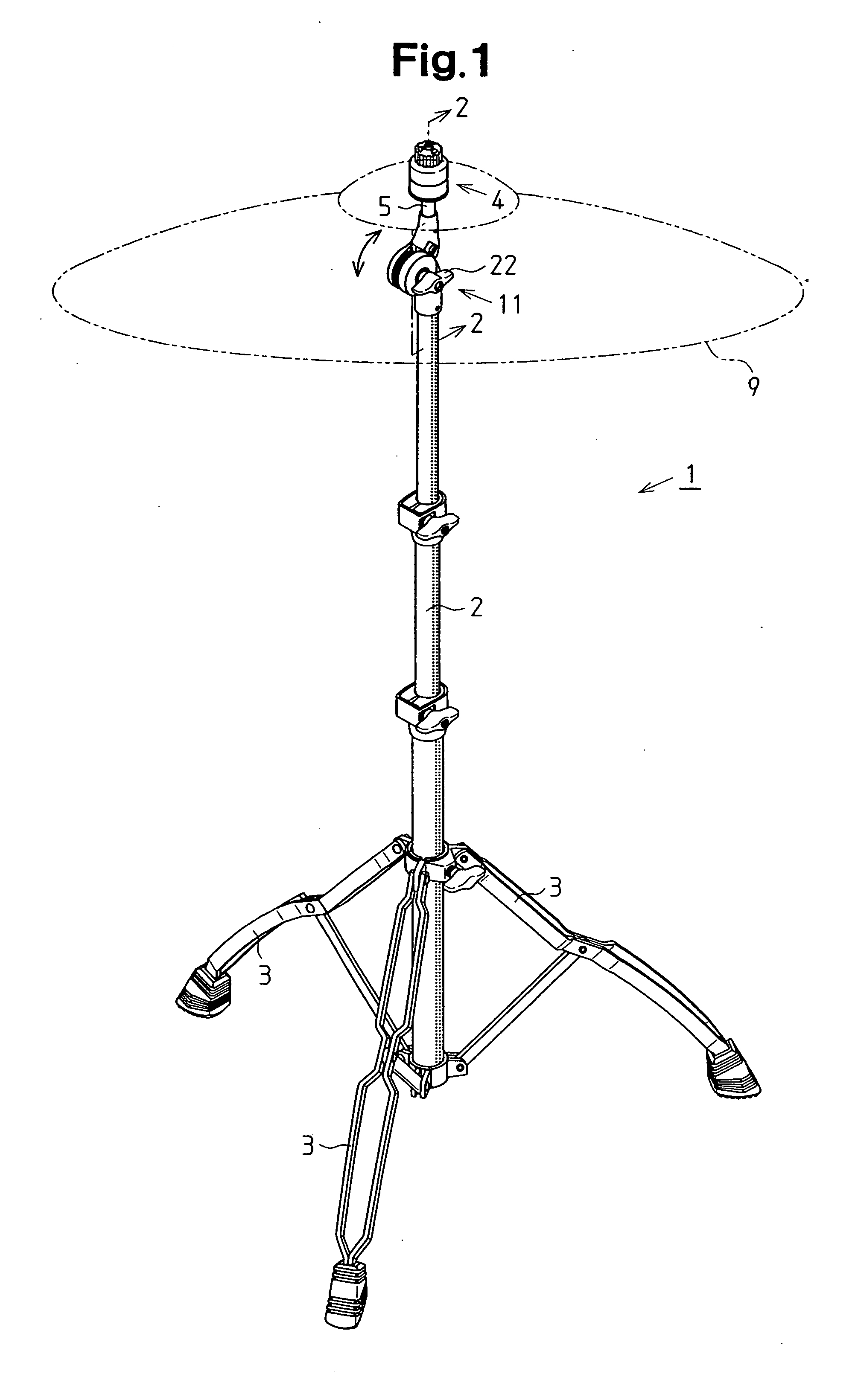
[0022] As shown in FIG. 1, a musical instrument stand 1 includes a pipe 2, which is supported by three legs 3 and extends upward, an angle adjustor 11 (hereafter, simply referred to as an “adjustor 11”), which is connected to the upper end of the pipe 2, and a musical instrument support 4, which is attached on the top of the adjustor 11. In the present embodiment, a cymbal 9 is held by the musical instrument support 4.
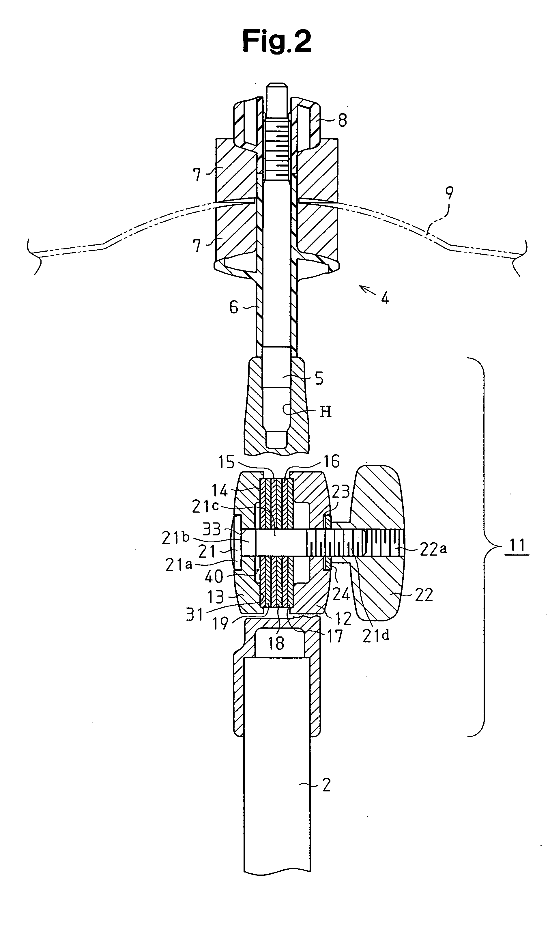
[0023] As shown in FIG. 2, the angle adjustor 11 includes a fixed member 12, a movable member 13, and a plurality of (six in the present embodiment) friction plates 14, 15, 16, 17, 18, and 19. The friction plates 14, 15, 16, 17, 18, and 19 are arranged between the fixed member 12 and the movable member 13. The angle adjustor 11 further includes a bolt 21, which extends into the movable member 13 from the outer side. The bolt 21 extends through the movable member 13, the friction plates 14 to 19, and the fixed member 12.
[0024] As shown in FIG. 3, the bolt 21 is a carr...
second embodiment
[0053] An angle adjustor 111 according to a second embodiment of the present invention will now be described, with reference to FIG. 7, focusing on parts differing from the first embodiment. The angle adjustor 111 of the second embodiment has the same structure as the first embodiment except in the fastening position of each screw 38, which functions as the fastener of the angle adjustor 11. The components of the angle adjustor 111 that are identical or equivalent to the components of the angle adjustor 11 are given the same reference numerals as those components and will not be described in detail.
[0054] As shown in FIG. 7, a pressing member 137 includes a plate-like head 145 and a functional piece 146 as in the first embodiment.
[0055] The pressing member 137 has a hole 148, through which the screw 38 is inserted. The hole 148 is located at a position closer to the first side wall 41a than the middle of the head 145. The hole 148 extends through the head 145 and the functional pi...
third embodiment
[0061] An angle adjustor 221 according to a third embodiment of the present invention will now be described with reference to FIG. 8. The second embodiment employs a pressing member 237 for the angle adjustor 221 that differs from the pressing member 137 of the angle adjustor 111 in the second embodiment. The pressing member 237 in the third embodiment does not have a part corresponding to the head 145 of the pressing member 137 in the second embodiment. Further, the pressing member 237 is formed only by a functional piece 246, which corresponds to the functional piece 146 of the pressing member 137 in the second embodiment.
[0062] Further, instead of the head 145, a plate-like cover 245 covers the top end opening 32a of the notch 32. The cover 245 is fixed to the top of the pressing member 237. Alternatively, the cover 245 may be fixed to the stepped portions 39. The cover 245 may be fixed to the pressing member 237 or stepped portions 39 by an adhesive, an adhesive tape, or a scre...
PUM
 Abstract
Description
Claims
Application Information
 - R&D
- Intellectual Property
- Life Sciences
- Materials
- Tech Scout
- Unparalleled Data Quality
- Higher Quality Content
- 60% Fewer Hallucinations
Browse by: Latest US Patents, China's latest patents, Technical Efficacy Thesaurus, Application Domain, Technology Topic, Popular Technical Reports.
© 2025 PatSnap. All rights reserved.Legal|Privacy policy|Modern Slavery Act Transparency Statement|Sitemap|About US| Contact US: help@patsnap.com


