Control apparatus for kite powered conveyance device

a control apparatus and conveyancing technology, applied in the direction of marine propulsion, toys, special-purpose vessels, etc., can solve the problems of kite control lines twisting about each, and affecting the safety of surfers

Inactive Publication Date: 2006-05-18
QUIJANO LUIS E
View PDF23 Cites 15 Cited by
  • Summary
  • Abstract
  • Description
  • Claims
  • Application Information

AI Technical Summary

Benefits of technology

[0006] The tether connector may be formed integrally with the swivel hook. Preferably, a spring urges the arm to extend from the spreader bar. The arm may include a quick release member enabling release of the arm from the spreader bar. The tether connector may include a rotor member and a shackle member pivotally attached to the rotor member, and the hook may be a snap hook.
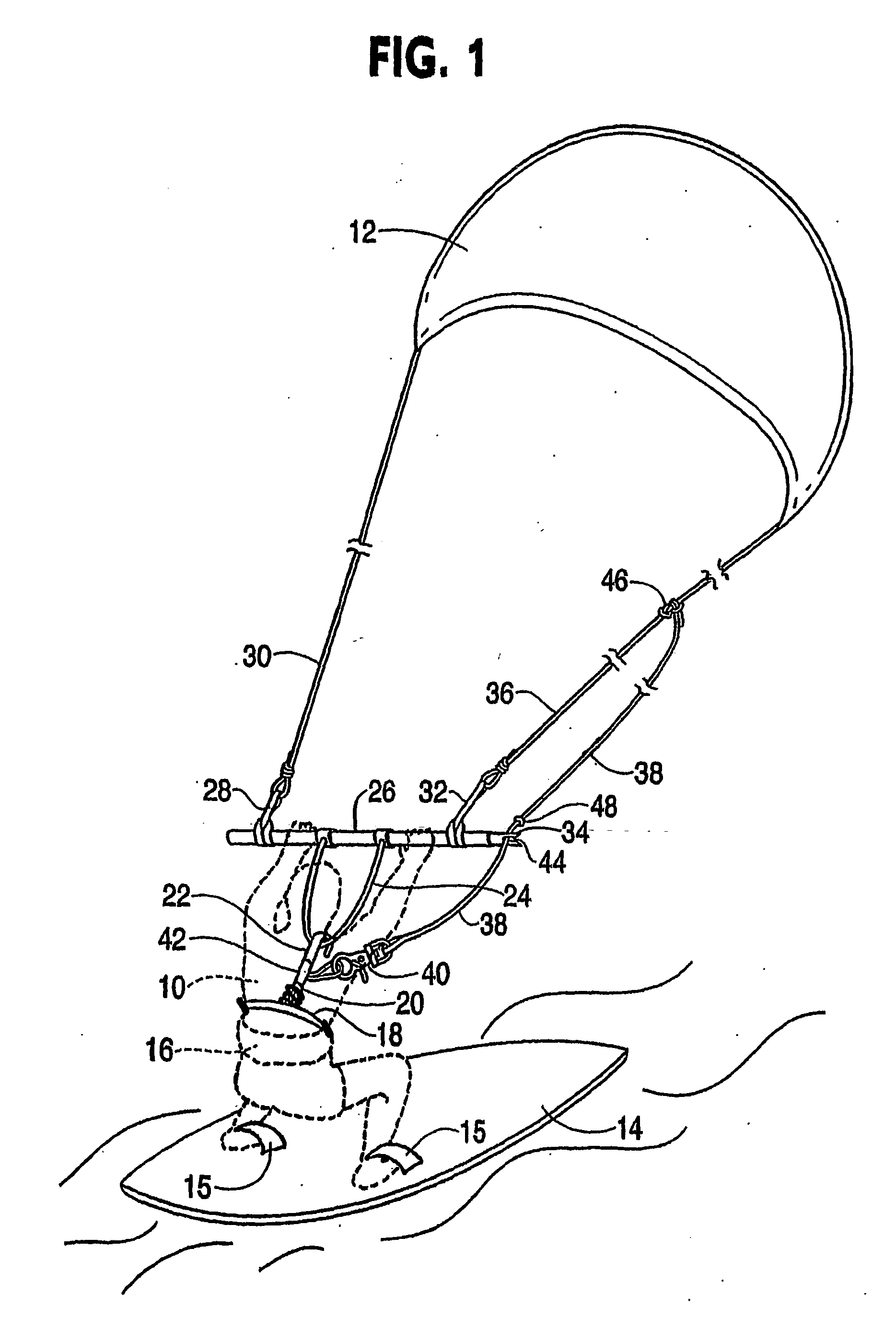
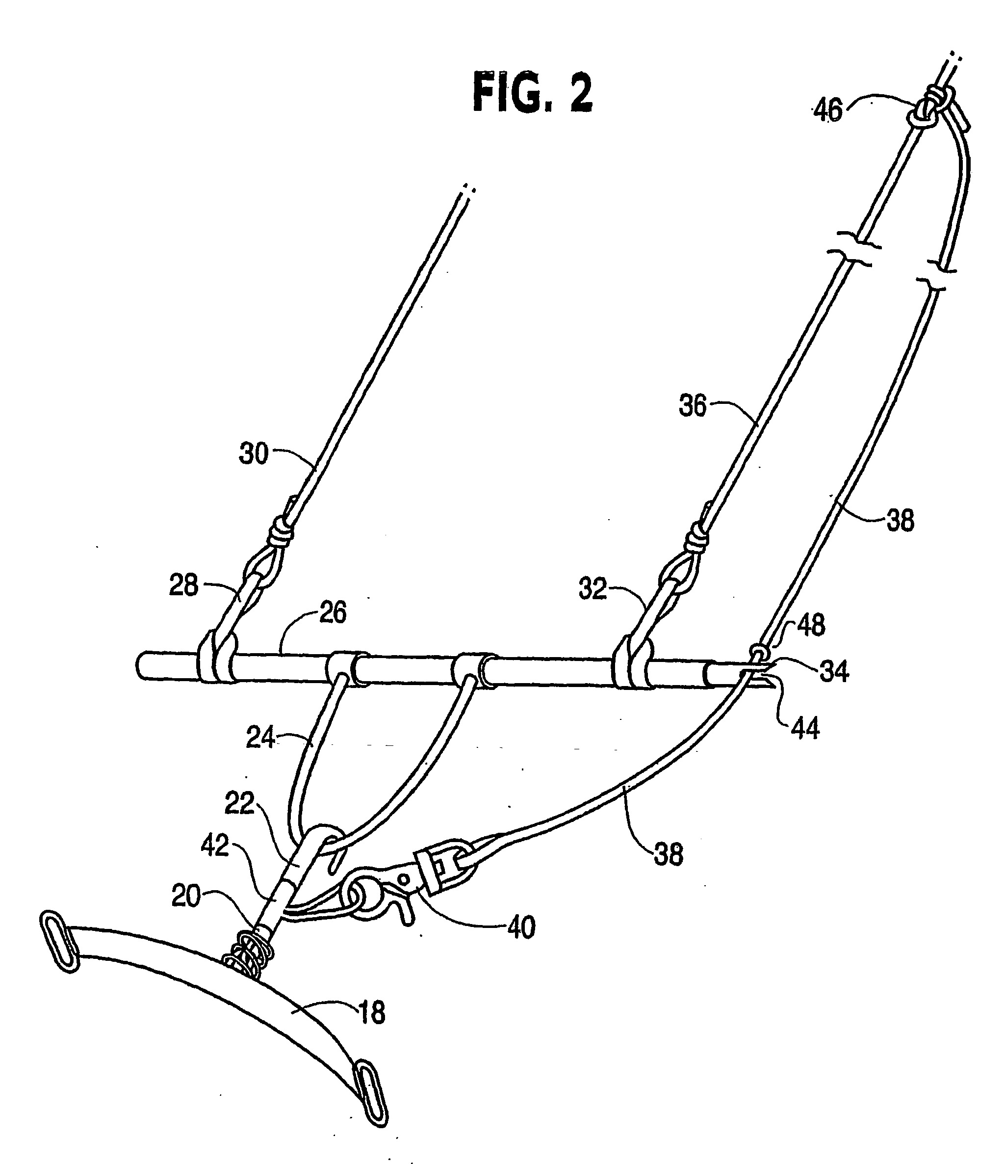
[0007] Further, in accordance with the present invention a control apparatus for a kite powered device includes a control bar adapted for connection by port and starboard kite leads and/or kite control lines to a kite of the kite powered device, a tether guide connected to an end of the control bar or adapted for connection to one of the kite leads, a spreader bar assembly as set forth above, and a tether connected to the tether connector, passing through the tether guide, and adapted for connection to one of the port and starboard kite control lines. Alternatively, the tether guide may be formed integrally with the control bar.
[0008] The tether guide may be a guide member having a first end connected to one end of the control bar or to one of the kite leads and a second end having a slot therein to receive the tether. Alternatively, the tether guide may be formed integrally with the control bar or with the kite leads. The slot preferably is sized in relationship to the tether to permit the tether guide to grip the tether in the slot, while allowing removal of the tether from the slot in response to pulling on the tether.
[0009] In addition, in accordance with the present invention, a kite powered conveyance device includes a kite having port a...

Problems solved by technology

The force on the tether, due to the wind in the kite, can result in considerable strain and damage to the surfers wrist, arm, and shoulder.
However, such stunts can result in the kite control lines twisting abou...

Method used


Image

  • Control apparatus for kite powered conveyance device
  • Control apparatus for kite powered conveyance device
  • Control apparatus for kite powered conveyance device

Examples


first embodiment

[0031]FIGS. 3 and 4 depict a spreader bar assembly in accordance with the present invention. Spreader bar 18 has a loop 54 at each end, permitting attachment of the spreader bar to harness 16. A U-shaped connector 56 extends from substantially the center of spreader bar 18. A second connector 58 extends from the end of arm 20. Connector 56 passes through an opening 60 in connector 58, connecting arm 20 to spreader bar 18 in a universal joint type connection. A washer 62 is rigidly fastened on arm 20. A coiled spring 64 encircles connectors 56 and 58 and extends between washer 62 and spreader bar 18, biasing arm 20 to extend from spreader bar 18.

[0032] Tether connector 42 is rotatably mounted on arm 20. Tether connector 42 includes a connection arm 66 which extends at an angle with the longitudinal axis of arm 20. Hook 22 is also rotatably mounted on arm 20. Tether connector 42 and hook 22 are retained in place and rotatable by suitable washers 67 and nuts 69, as appropriate, with ar...

second embodiment

[0033]FIGS. 5 and 6 depict a spreader bar assembly in accordance with the present invention which differs from the embodiment of FIGS. 3 and 4 by replacing hook 22 and tether connector 42 of FIGS. 3 and 4 with an integral hook and connector 68. In addition, both a port connection arm 66p and a starboard connection arm 66s are provided, permitting the selection of the side of kite 12 to which tether 38 is connected.

[0034]FIG. 7 depicts another embodiment of a control apparatus for a kite powered device in accordance with the present invention. Tether rotor 42′ is mounted on connector 58′, being freely rotatably thereon. Arm 20′ is inserted into opening 70 of connector 58′ and held within that opening by quick release pin 72 which passes through a second opening through connector 58′ and arm 20′. Tether rotor 42′ is a circular disk and preferably is positioned between two sets of washers and nuts (not shown) on connector 58′. Snap hook 40 on the end of tether 38 is connected to D shac...


PUM


Abstract

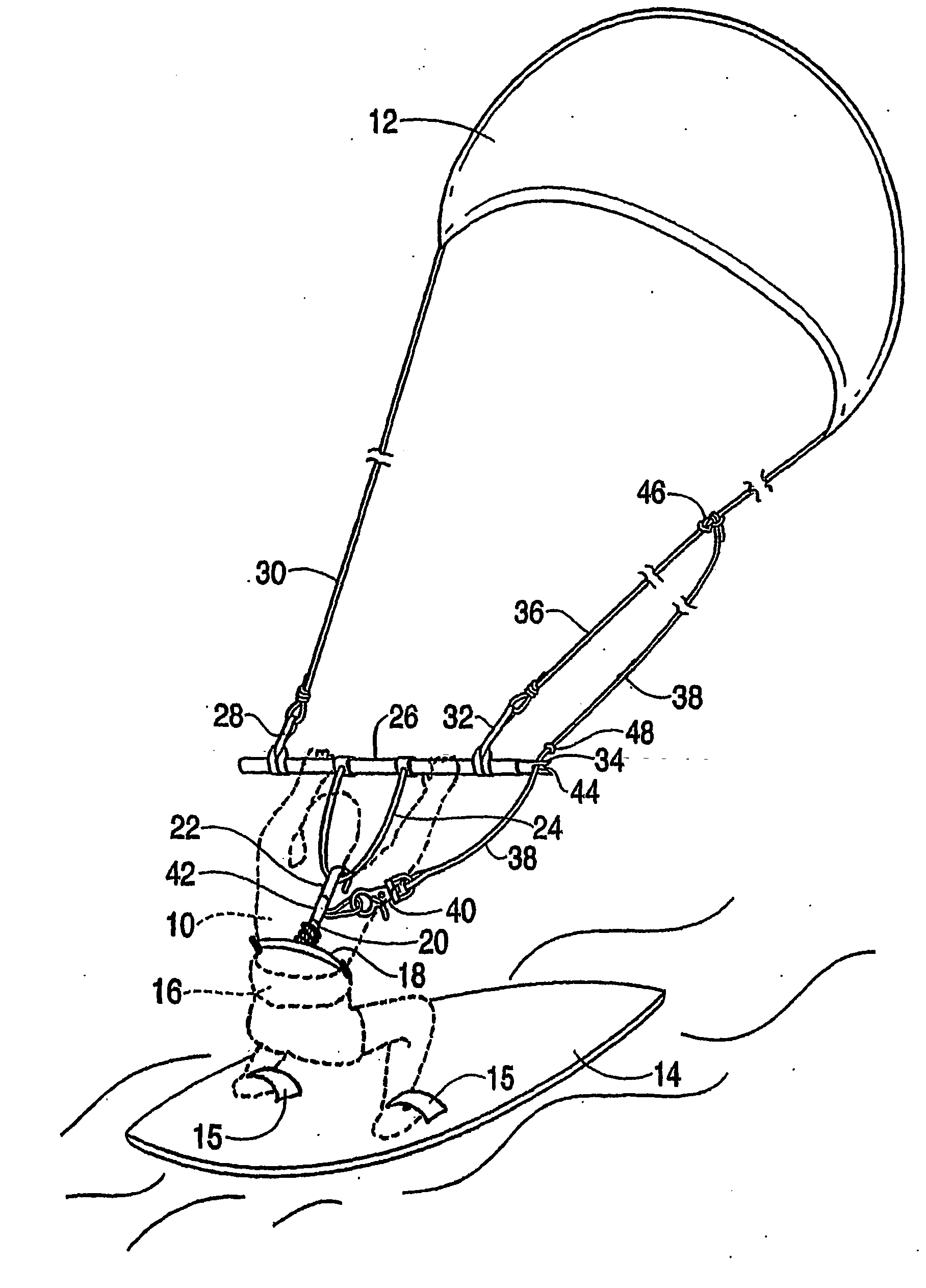
A control apparatus for a kite powered conveyance device. Port and starboard kite leads (28,32) and/or port and starboard kite control lines (30, 36) connect ends of a control bar (26, 26′) to port and starboard ends of a kite (12). A tether guide (34, 34′, 34″) is connected to one end of the control bar (26) or to one of the kite leads (28, 32). A harness (12) with a spreader bar (18) is adapted to be worn by a user of the kite powered conveyance device. An arm (20, 20′) is connected to the spreader bar (18). A tether connector (42, 42′) and a hook (22, 22′) are rotatably mounted on the arm (20, 20′) for rotation about the longitudinal axis of the arm (20, 20′). The hook (22, 22′) is hooked to the control bar (26, 26′) to connect the control bar (26, 26′) to the spreader bar (18). A tether (38) passes through the tether guide (34, 34′, 34″) and has its first end connected to the tether connector (42, 42′) and its second end connected to one of the Kite control lines (30, 36).

Description

CROSS-REFERENCE TO RELATED APPLICATION [0001] This application claims the benefit of U.S. Provisional Patent Application Ser. No. 60 / 399,033 filed Jul. 29, 2002.TECHNICAL FIELD [0002] The present invention pertains to a control apparatus for a kite powered conveyance device. More particularly, the present invention pertains to a spreader bar assembly permitting improved control of a kite powered conveyance device, such as a surfboard, in line skates, or a similar conveyance device. BACKGROUND ART [0003] Kite powered conveyance devices are becoming increasingly popular for recreational purposes. By way of example kite surfing, such as depicted in FIG. 1, has rapidly become a popular water sport. In kite surfing, a person stands on a surfboard and grips a control bar which is fastened by kite control lines to opposite sides of a large kite. The person may wear a harness with a spreader bar which is hooked to the control bar. As the kite is blown by the wind, the kite tows the person o...

Claims


Application Information

Patent Timeline
IPC IPC(8): A63H27/00B63B35/79
CPCB63B35/7979B63B35/7993B63H8/16B63H8/18B63H8/58
Inventor QUIJANO, LUIS E.
Owner QUIJANO LUIS E
Why Eureka
Try Eureka