Vehicle back up camera

Inactive Publication Date: 2006-05-18
TSENG HUAN CHIN
3 Cites 399 Cited by

AI-Extracted Technical Summary

Problems solved by technology

Therefore the conventional back up camera needs a large waterproof housing to cover all the components and occupies a l...

Benefits of technology

[0006] The main objective of the present invention is to provide a separate back up camera for a vehicle, particularly an automobile. The separate vehicle back up camera has a photo-device, at least one electric wire, a circuit board and a signal Wire. The at least one electric wire connects t...

Abstract

A separate vehicle back up camera has a photo-device, at least one electric wire, a circuit board and a signal wire. The at least one electric wire connects the photo-device to the circuit board. The signal wire connects to the circuit board to transmit signal inside the vehicle. The photo-device and the circuit board are mounted separately in the vehicle so the photo-device can be concealed well and will not detract from the appearance of the vehicle.

Application Domain

Television system detailsColor television details +2

Technology Topic

Electrical and Electronics engineeringElectric wire

Image

  • Vehicle back up camera
  • Vehicle back up camera
  • Vehicle back up camera

Examples

  • Experimental program(1)

Example

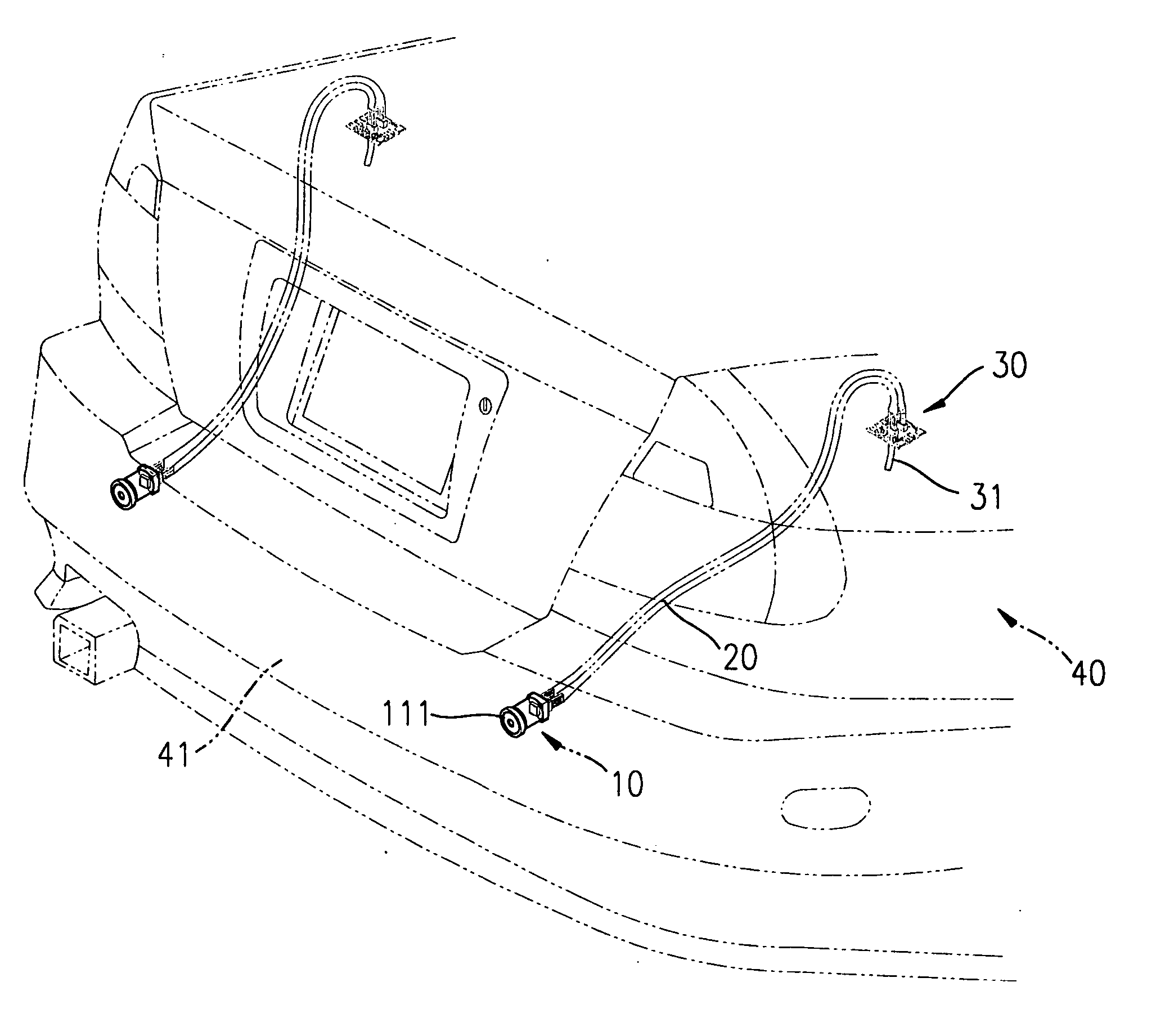
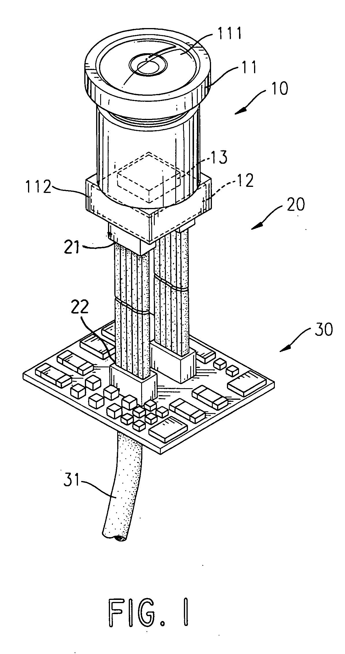
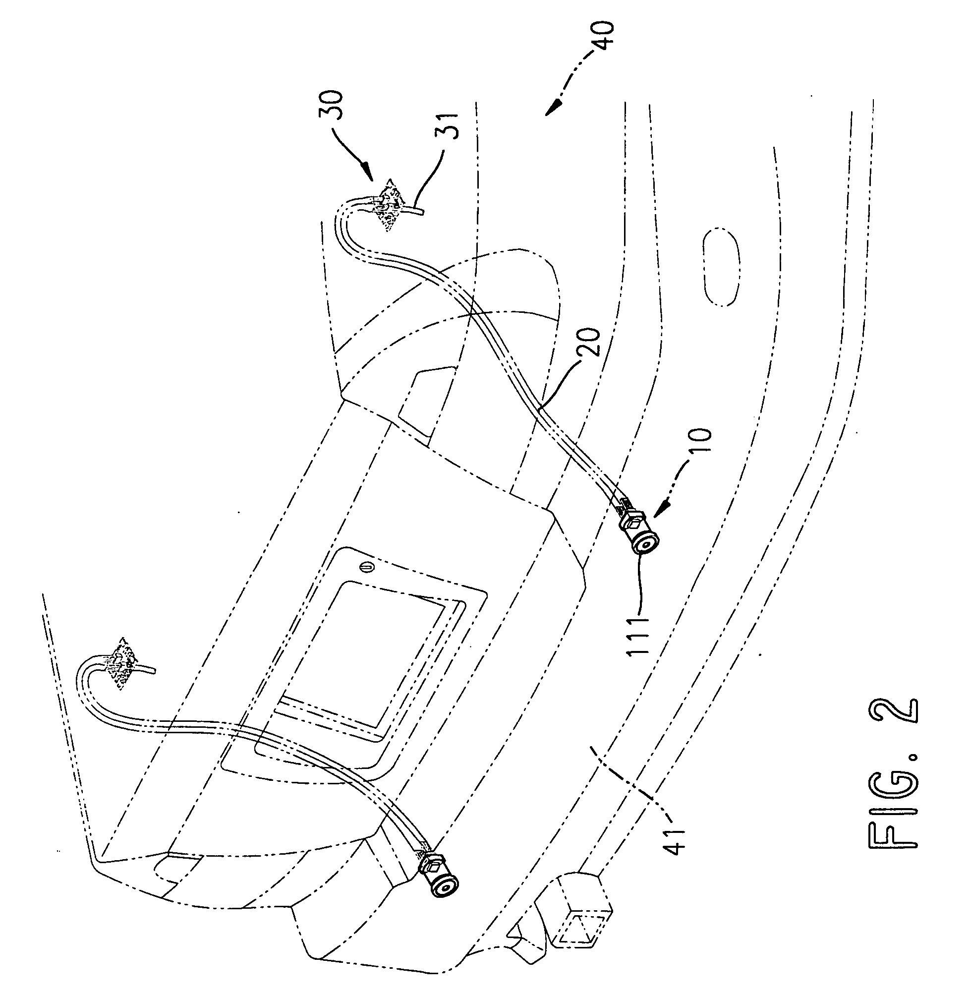
[0011] With reference to FIG. 1, a separate vehicle back up camera in accordance with the present invention comprises a photo-device (10), a circuit board (30), at least one electric wire (20) and a signal wire (31).
[0012] The photo-device (10) comprises a distal end, a proximal end, a head (11), a lens (111), a sensor recess (112), a sensor (12) and a filter (13). The head (11) is formed on the distal end. The lens (111) is mounted securely in the head (11). The sensor recess (112) is formed in the proximal end. The sensor (12) is mounted securely in the sensor recess (112) and may be a charge coupled device (CCD). The filter (13) is attached to the sensor (12).
[0013] The circuit board (30) has an input side and an output side.
[0014] Each electric wire (20) connects the photo-device (10) to the circuit board (30) and has an input end (21) and an output end (22). The input end (21) connects to the sensor (12). The output end (22) connects to the input side of the circuit board (30). In the preferred embodiment, the back up camera has two electric wires (20).
[0015] The signal wire (31) connects to the output side of the circuit board (30) to transmit signals inside the vehicle.
[0016] With further reference to FIG. 2, the separate back up camera is mounted in an automobile (40). The automobile (40) has a rear end and a rear bumper (41). The rear bumper (41) is attached to the rear end of the automobile (40). The photo-device (10) is mounted in the rear bumper (41). The circuit board (30) is mounted inside the automobile (40). Because the at least one electric wire (20) connects the photo-device (10) to the circuit board (30), the photo-device (10) and the circuit board (30) can be mounted in different locations in the automobile (40). Therefore the photo-device (10) can be well concealed and will not detract from the appearance of the automobile (40).
[0017] Even though numerous characteristics and advantages of the present invention have been set forth in the foregoing description, together with details of the structure and features of the invention, the disclosure is illustrative only. Changes may be made in the details, especially in matters of shape, size, and arrangement of parts within the principles of the invention to the full extent indicated by the broad general meaning of the terms in which the appended claims are expressed.

PUM

no PUM

Description & Claims & Application Information

We can also present the details of the Description, Claims and Application information to help users get a comprehensive understanding of the technical details of the patent, such as background art, summary of invention, brief description of drawings, description of embodiments, and other original content. On the other hand, users can also determine the specific scope of protection of the technology through the list of claims; as well as understand the changes in the life cycle of the technology with the presentation of the patent timeline. Login to view more.
Why Eureka
Try Eureka