Roller blind system

a technology of roller blinds and rollers, applied in the field of roller blinds, can solve the problems of more acute problems and respect for the functioning condition

Inactive Publication Date: 2012-11-15
BOS
View PDF11 Cites 1 Cited by
  • Summary
  • Abstract
  • Description
  • Claims
  • Application Information

AI Technical Summary

Problems solved by technology

There are, nevertheless, disadvantages, in particular with respect to the functioning condition.
Thus in the functioning condition, in which the pull-out profile is located in the region of the roof liner, the smaller cross-section in the region of the main segment leaves a gap open to the light, even if the roof liner is entirely flat, and this is felt to be ...

Method used


Image

  • Roller blind system
  • Roller blind system
  • Roller blind system

Examples


Embodiment Construction

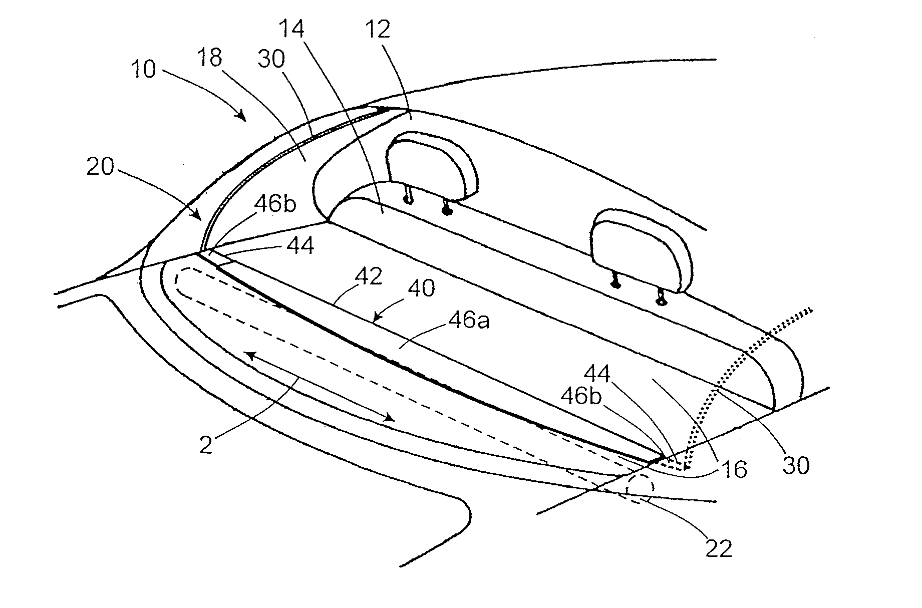
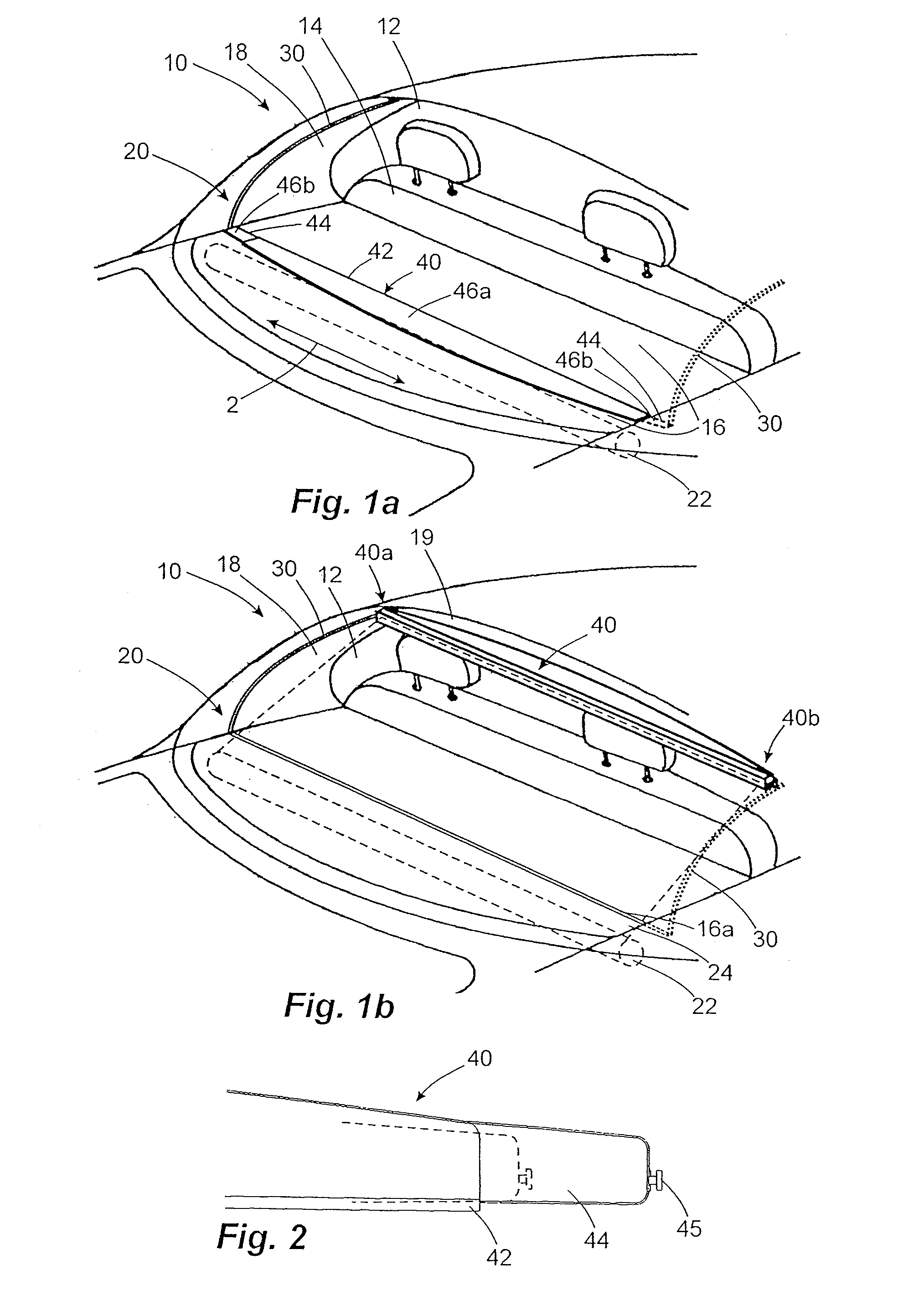
[0030]FIGS. 1a and 1b illustrate the rear region of a vehicle 10, providing a view through the rear window 12 to the area of a rear vehicle seat 14 and of a parcel shelf 16 positioned behind it.

[0031]A roller blind system 20 is provided in order to provide shade at the rear window 12. This roller blind system 20 incorporates a winding shaft 22 on rotating bearings and located underneath the parcel shelf 16, onto which, when in the stowed condition of FIG. 1a, a flexible fabric sheet 24, consisting for instance of textile, is wound. This fabric sheet 24 can be unwound from the winding shaft 22 through an exit slot 16a provided in the parcel shelf, in order to reach the functioning condition of FIG. 1b.

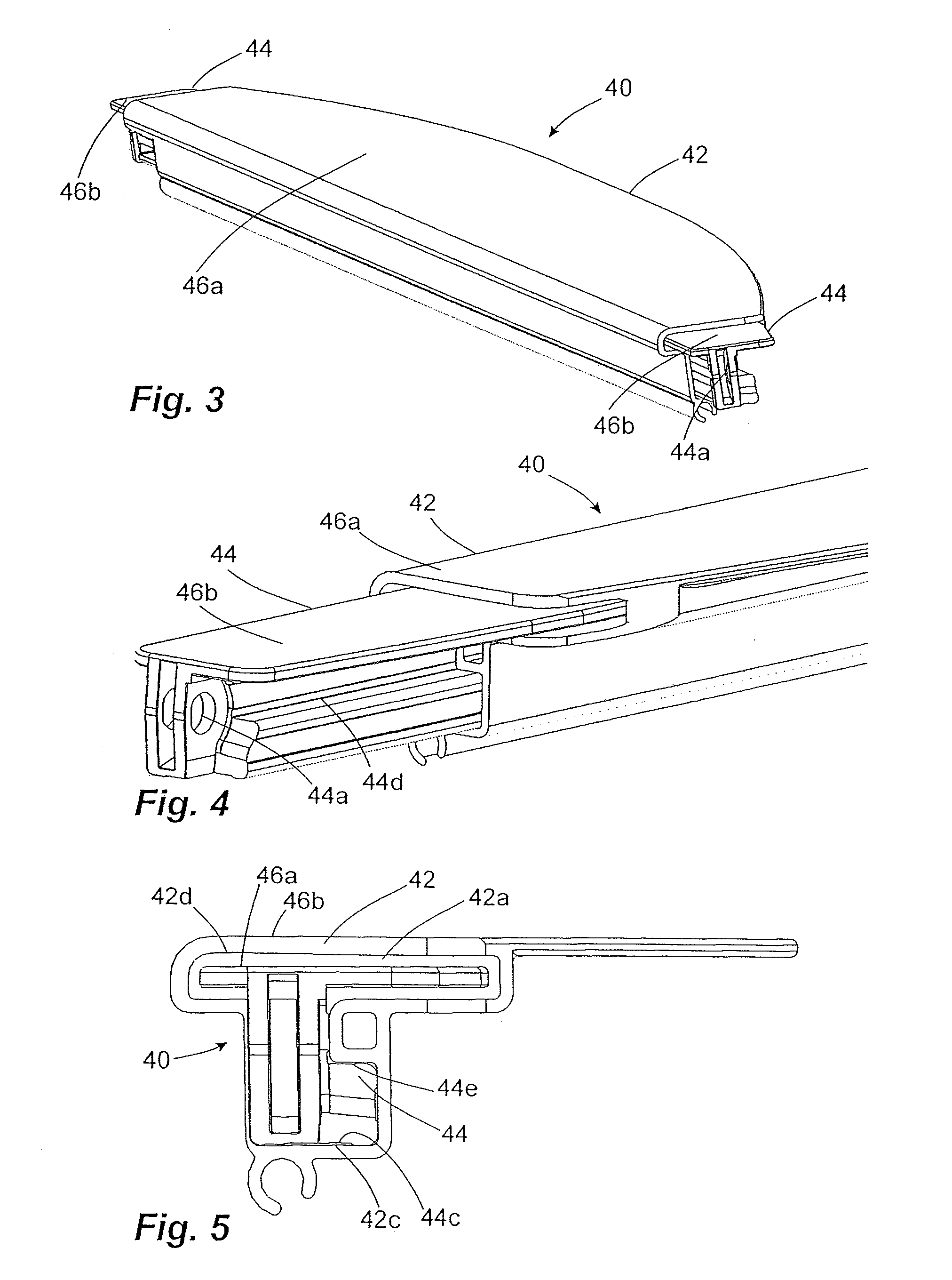
[0032]For the purposes of this move into the functioning condition of FIG. 1b, a pull-out profile 40 is provided at the distal end of the trapezoidal fabric sheet 24. This pull-out profile can be moved, guided by guide rails 30, by means of sliding pieces, not shown in more detail in F...


PUM


Abstract

A roller blind system for a vehicle for shading a rear window, having a fabric sheet movable between stowed and functioning conditions, with a pull-out profile provided at a distal end thereof and two guide rails located on sides of the sheet, whereby the pull-out profile incorporates two sliding pieces at its opposite ends each engaged with one guide rail. The pull-out profile covers an outlet slot for the sheet. The pull-out profile has a variable length and includes a main segment bonded to the sheet and two movable end segments movable relative to the main segment by a guide. The covering face comprises a main section on the main segment and side sections on the end segments. The side sections enter into a receiving pocket enclosed by the main segment when the length of the pull-out profile is reduced.

Description

CROSS REFERENCE TO RELATED APPLICATION[0001]This application claims the priority of German Application No. 10 2011 075 843.7, filed May 13, 2011, the disclosure of which is hereby incorporated by reference in its entirety into this application.FIELD OF APPLICATION AND PRIOR ART[0002]The invention concerns a roller blind system for a motor vehicle, in particular for giving shade at a rear window of the motor vehicle.[0003]A generic roller blind system of this sort comprises a flexible fabric sheet provided particularly for the purpose of covering the window and capable of being moved between a stowed condition and a functioning condition. It includes, furthermore, at a distal end of the fabric sheet, a pull-out profile and two guide rails that are arranged on both sides of the fabric sheet when it is in its functioning condition, and which are aligned, at least partially, not parallel to one another. For the purposes of guided movement along the guide rails, the pull-out profile inco...

Claims


Application Information

Patent Timeline
IPC IPC(8): B60J3/02
CPCB60J1/208B60J1/2044
Inventor WEINBRENNER, HARRY
Owner BOS
Why Eureka
Try Eureka