Flap arrangement and aircraft with at least one flap arrangement

a flap arrangement and flap technology, applied in the direction of wing lift eficiency, wing adjustment, weight reduction, etc., can solve the problems of significant constraint force, statically over-determined overall system, and constraint force occurring between the basic body and the flap, so as to prevent the deviation of excess shape between the flap and the basic body

Active Publication Date: 2016-04-19
AIRBUS OPERATIONS GMBH
View PDF24 Cites 11 Cited by
  • Summary
  • Abstract
  • Description
  • Claims
  • Application Information

AI Technical Summary

Benefits of technology

[0012]Analogous to the aforesaid, thus by limiting the rigid connection to the basic body and to the flap to two bearing points it is possible from a statically over-determined system to achieve a statically determined system in which load-induced deformation may be compensated for even with the flap angled out. The movability of the local connection between the flap, the remaining bearing points and the basic body result in no constraint forces, except for a minimum, arising in the respective other body.
[0032]In an advantageous embodiment at least one sealing element is arranged on the flap, which sealing element extends to the basic body and may be displaced in the base body or relative to the base body. The sealing element improves the aerodynamic quality of the flap arrangement, because influencing the flow around the flap arrangement by a slot flow or gap flow is largely prevented. Furthermore, paint damage to the flap components or the leading edge components of control surfaces is largely prevented. Because of the movable connection between the bearing points, which are arranged between the outer bearing points, and the flap, adequate movement for the at least one sealing element is to be provided. For reliable covering of the gaps, the sealing element can be designed so as to be elastic and / or spring-loaded.

Problems solved by technology

However, as a result of attaching a movable flap to the base body by means of a hinge arrangement the overall system is statically over-determined.
In particular when exterior forces, for example, forces resulting from air or inertia, act on the system, this results in constraint forces occurring between the basic body and the flap.
This results in significant constraint forces in particular if the flap assumes a deflected position relative to the basic body.

Method used


Image

  • Flap arrangement and aircraft with at least one flap arrangement
  • Flap arrangement and aircraft with at least one flap arrangement
  • Flap arrangement and aircraft with at least one flap arrangement

Examples


Embodiment Construction

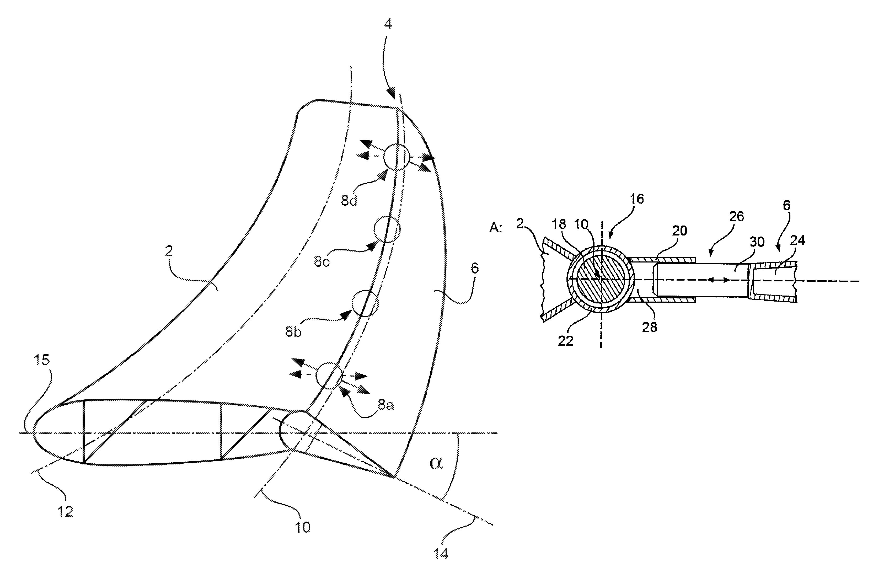
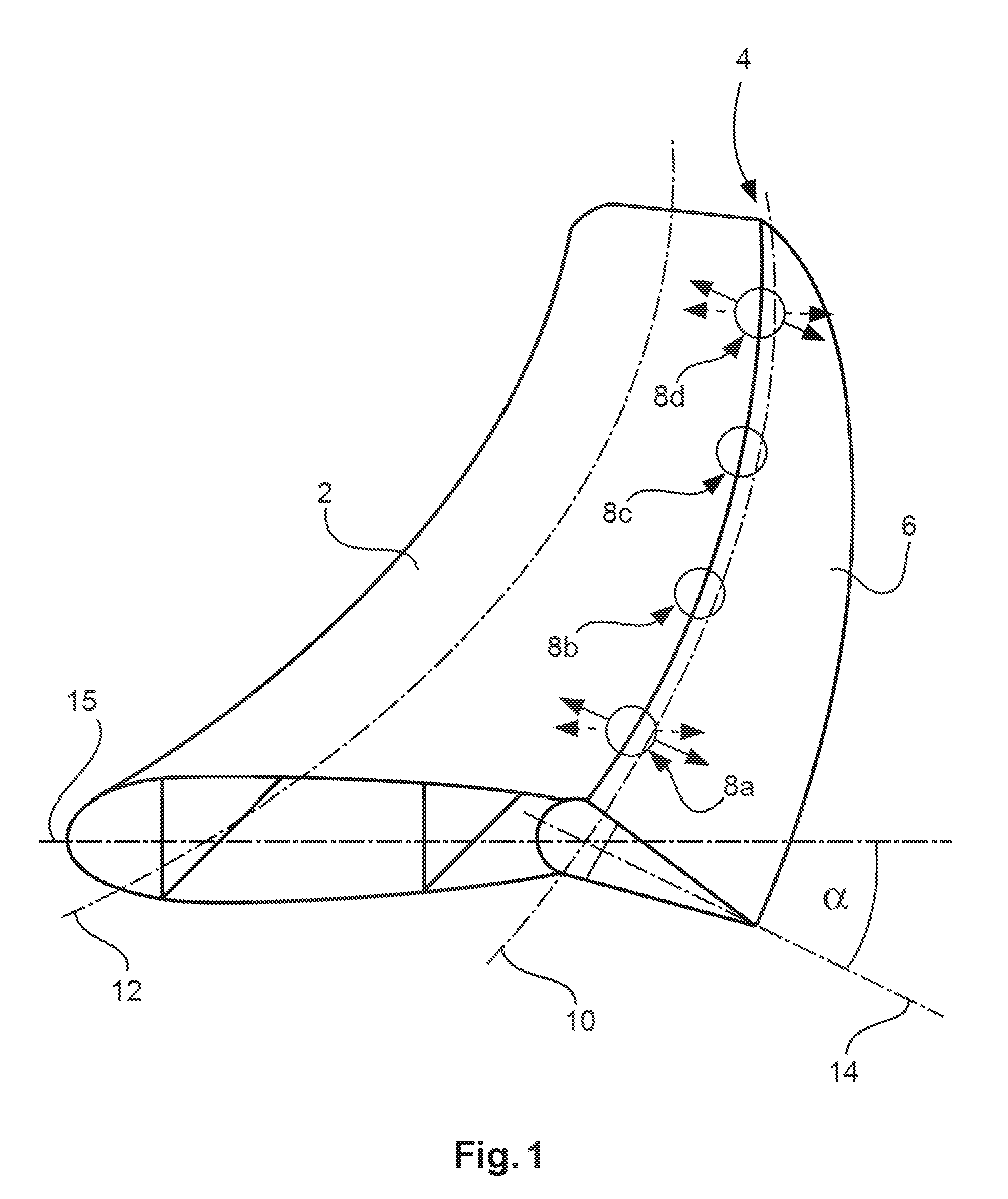
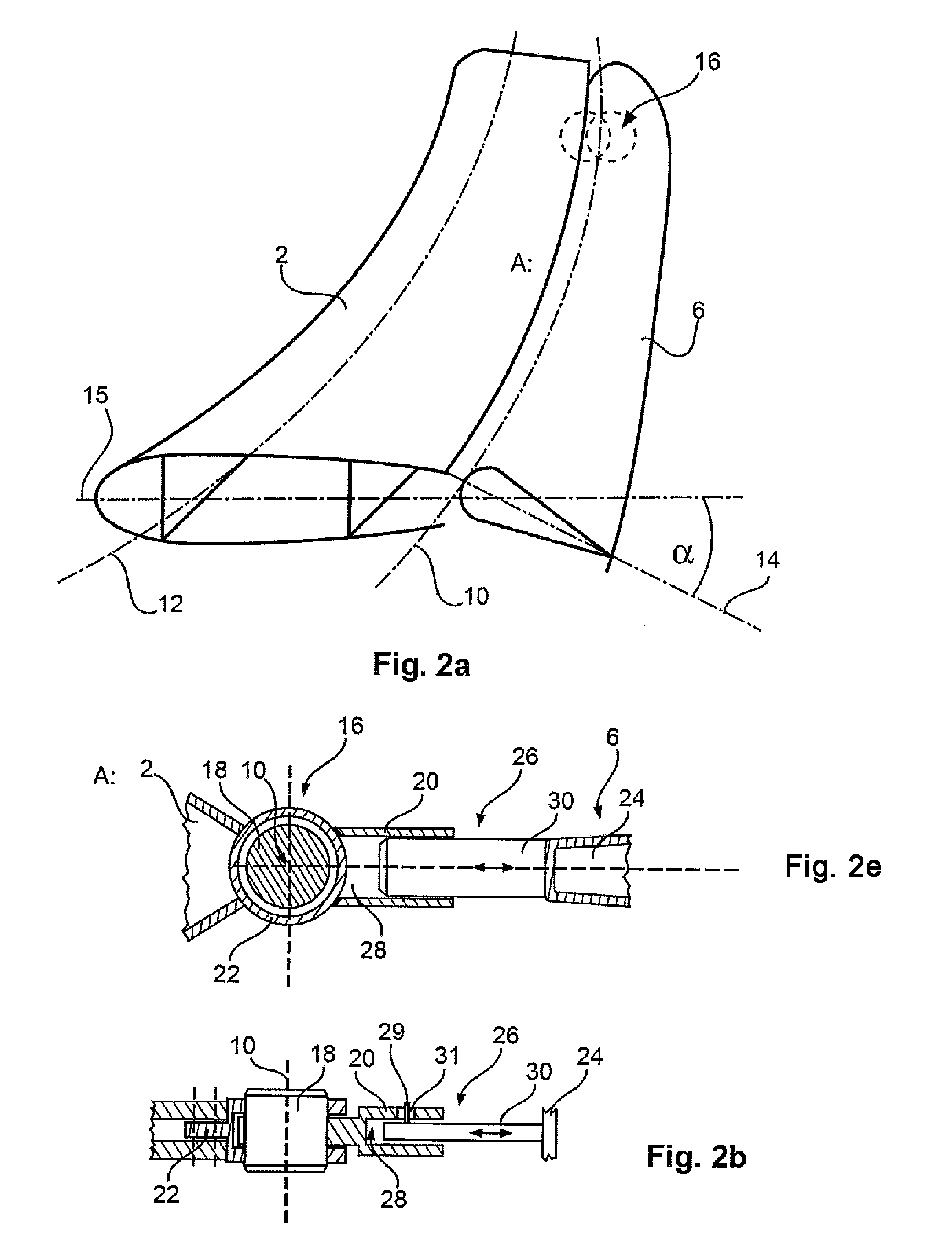
[0044]FIG. 1 shows a diagrammatic view of the fundamental principle of an embodiment of the invention. A basic body 2 comprises a hinge arrangement 4 by way of which a flap 6 is movably held on the basic body 2. The hinge arrangement 4 comprises several bearing points 8a to 8d that are spaced apart from each other and arranged on a shared hinge line 10. The illustration may, for example, show a vertical stabilizer, wherein the basic body 2 is a tail unit body whose one end is rigidly attached to an aircraft fuselage. As a result of the action of external aerodynamic loads, elastic deformation of the basic body 2 occurs, as is shown by the deformed longitudinal axis 12.

[0045]With the use of, for example, four bearing points 8a to 8d, in the case of a continuous rigid connection to all the bearing points 8a to 8d the flap 6 would be force-guided. Consequently the flap 6 would have to deform to such an extent that both the bending line of the basic body 2 and control by an actuator to ...


PUM


Abstract

A flap arrangement includes a basic body, a hinge arrangement, and a flap that by the hinge arrangement is movably held on the basic body. The hinge arrangement includes at least three bearing points spaced apart from each other and arranged on a shared hinge line, wherein two bearing points are rigidly connected to the basic body and to the flap, and wherein the remaining bearing points in each case allow local movement between the basic body and the flap in at least one first spatial direction perpendicularly to the hinge line. Thus, load-induced constraint forces between the basic body and the control surface can be prevented.

Description

CROSS-REFERENCE TO RELATED APPLICATIONS[0001]This application claims the benefit of the filing date of U.S. Provisional Patent Application No. 61 / 616,010, filed Mar. 27, 2012, the disclosure of which is hereby incorporated herein by reference.TECHNICAL FIELD[0002]The invention relates to a flap arrangement and an aircraft with at least one flap arrangement.BACKGROUND OF THE INVENTION[0003]For controlling an aircraft, usually control surface arrangements or flap arrangements are used that are, in particular, arranged on trailing edges of wings or tail units. Attaching pivotable flaps is possible in various ways. Relatively small flaps may, for example, be mounted by way of a hinge arrangement with two points of articulation on a basic body in order to ensure the introduction of forces between the flap and the basic body in question. Where relatively slender and long flaps are used it is, however, necessary to use a hinge arrangement with more than just two points of articulation whic...

Claims


Application Information

Patent Timeline
Patent Type & Authority Patents(United States)
IPC IPC(8): B64C9/02
CPCB64C9/02Y02T50/32Y02T50/44Y02T50/30Y02T50/40
Inventor MAENZ, CHRISTIAN
Owner AIRBUS OPERATIONS GMBH
Why Eureka
Try Eureka