High dynamic range images from low dynamic range images

Active Publication Date: 2006-05-18
SHARP KK
View PDF99 Cites 83 Cited by
  • Summary
  • Abstract
  • Description
  • Claims
  • Application Information

AI Technical Summary

Problems solved by technology

More extreme range changes, such as going into a movie theatre from daylight, can take more than a minute.
But the

Method used


Image

  • High dynamic range images from low dynamic range images
  • High dynamic range images from low dynamic range images
  • High dynamic range images from low dynamic range images

Examples


Embodiment Construction

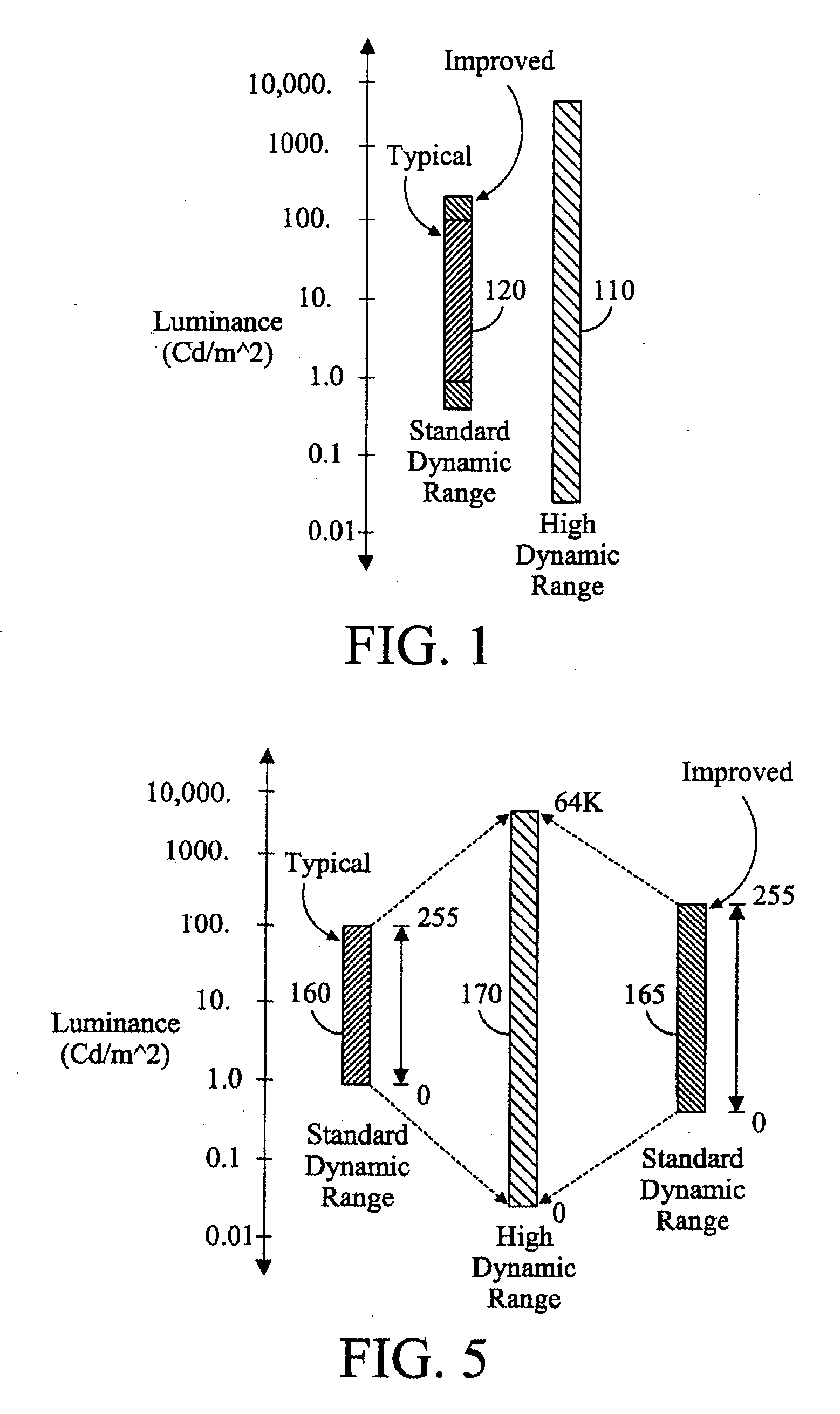
[0031] Newly developed displays have been made which have substantially higher dynamic range than the traditional state of the art displays. The general difference in dynamic ranges for the newly developed displays 110 and the traditional displays 120 is shown in FIG. 1 for a log luminance scale. Some current state of the art standard dynamic range displays may have a range of 500 cd / mˆ2 to 0.7 cd / mˆ2. The newly developed “high dynamic range” displays may have a range from 3000 cd / mˆ2 to 0.05 cd / mˆ2, or even lower. In existing display technologies the image data is displayed on the display with its existing dynamic range.

[0032] The present inventors came to the realization that the image being presented on the display could be subjectively improved if the dynamic range of the image data is effectively increased. Since most images are already represented in a LDR (low dynamic range) format, a technique is desirable to convert the image from LDR up to HDR (high dynamic range).

[0033]...


PUM


Abstract

A method for displaying an image includes receiving an image having a first luminance dynamic range and modifying the image to a second luminance dynamic range free from being based upon other images, where the second dynamic range is greater than the first dynamic range. The modified image is displayed on a display.

Description

CROSS-REFERENCE TO RELATED APPLICATIONS [0001] This application claims the benefit of U.S. Ser. No. 60 / 628,762 filed Nov. 16, 2004 entitled Using Spatial Assessment to Increate the Dynamic Range of Imagery and claims the benefit of U.S. Ser. No. 60 / 628,794 filed Nov. 16, 2004 entitled Generating High Dynamic Range Data.BACKGROUND OF THE INVENTION [0002] The present application relates to increasing the dynamic range of images. [0003] Many scenes existing in the real world inherently have extremely high dynamic range. For example, white paper in full sunlight has a luminance level of 30,000 cd / mˆ2, while white paper in the full moon has a luminance level of 0.01 cd / mˆ2, giving a dynamic range of 3 million to one (or 6.4 log units). The human eye can see even dimmer levels than 0.01 cd / mˆ2, so the visible range is even greater. In most situations, the dynamic range of a single scene is usually not this great, but it is frequently in excess of 5 log units. The human eye can only see 2-...

Claims


Application Information

Patent Timeline
IPC IPC(8): G06K9/40
CPCG06T5/009G06T5/50G06T2207/20208G09G2320/0271
Inventor DALY, SCOTT J.MEYLAN, LAURENCE
Owner SHARP KK
Why Eureka
Try Eureka