Flow distribution apparatus

a technology of fluid distribution apparatus and flow, which is applied in the direction of ion exchangers, separation processes, filtration separation, etc., can solve the problems of significant movement of particles in the contact bed, and achieve the effect of reducing or eliminating high velocity jets and/or other turbulen

a technology of fluid distribution apparatus and flow, which is applied in the direction of ion exchangers, separation processes, filtration separation, etc., can solve the problems of significant movement of particles in the contact bed, and achieve the effect of reducing or eliminating high velocity jets and/or other turbulen

US20060108274A1Active Publication Date: 2006-05-25UOP LLC

Image

  • Flow distribution apparatus
  • Flow distribution apparatus
  • Flow distribution apparatus

Examples


Embodiment Construction

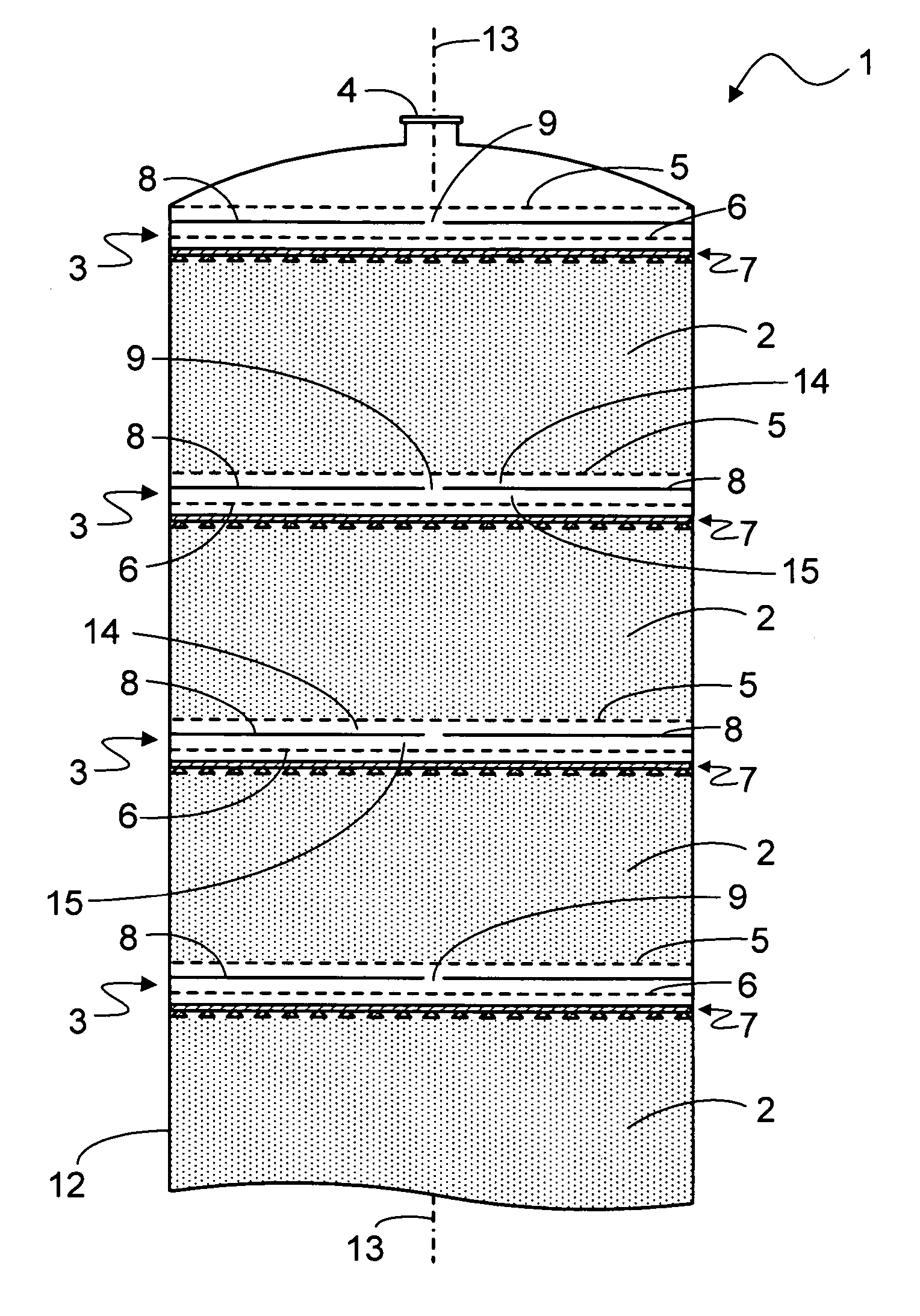
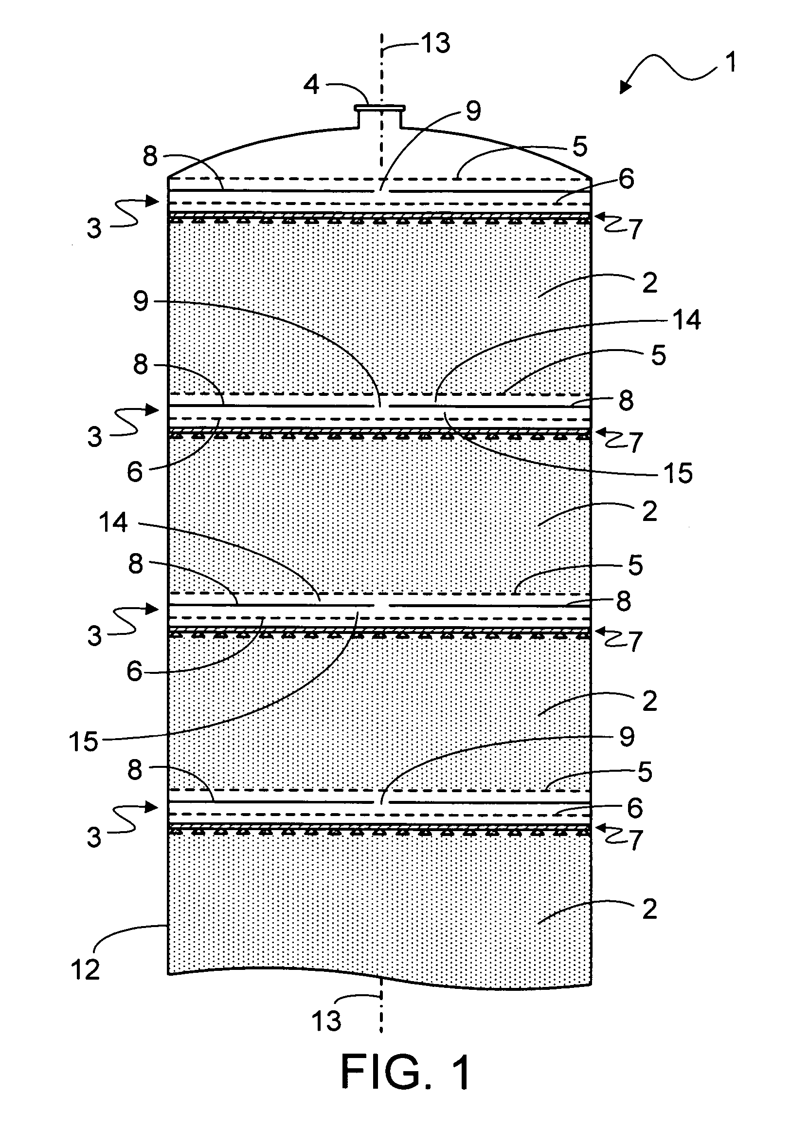
[0011] The subject invention may be used in any process wherein fluid is contacted with solid particles which are divided into a plurality of beds contained in a vessel. The vessel is oriented vertically along its major axis. Although such vessels are typically cylindrical and thus have a circular cross sectional shape, the subject invention is not limited by the cross sectional shape of the vessel. The process may employ one or more such vessels. The fluid flows downwardly in the vessel through the solid particle beds which are separated by mixer-distributor-collectors. Myriad solid particles are used in such processes. Non-limiting examples of groups of such materials each of which have many specific compositions and physical forms include adsorbents, resins, catalysts, and inert materials. The fluid may be a vapor, liquid or supercritical fluid. Although the invention is not intended for multiple fluid phases, the fluid may contain many compounds or be a mixture of multiple fluid...


PUM

PropertyMeasurementUnit
diameteraaaaaaaaaa
diameteraaaaaaaaaa
distanceaaaaaaaaaa

Abstract

Disclosed is a mixer-distributor-collector apparatus for use between beds of solid particles in a fluid-solid contacting vessel. The apparatus includes a solids retaining screen, fluid deflector, passageway, fluid distributor, and flow manipulator. The flow manipulator is a device such as a honeycomb, porous solid, perforated plate, screen, or grid having an open area greater than the open area of the fluid distributor and is located below and spaced apart from the fluid distributor. The apparatus improves the fluid flow characteristics by minimizing or eliminating fluid velocity jets and / or other turbulence which can disturb the downstream particle bed. In an exemplary application, the invention finds use in simulated moving bed (SMB) adsorptive separation processes.

Description

FIELD OF THE INVENTION [0001] The subject invention relates to apparatus used to distribute and / or mix fluid. More specifically, the invention relates to an apparatus that distributes and / or mixes fluid flowing in a vessel containing solid particles. In an exemplary application, this invention finds use in simulated moving bed (SMB) adsorptive separation processes. BACKGROUND OF THE INVENTION [0002] Various apparatus that mix and / or distribute fluid as it flows through a vessel containing solid particles are well known in the art. One or more such devices may be positioned within a vessel and divide the solid particles into two or more beds. The use of such fluid distributing devices can increase the efficiency of operations by providing more uniform fluid properties across the cross-sectional area of the vessel. For example, they can minimize or eliminate flow rate variations or channeling; temperature differences; and variations in the fluid composition. These apparatus may also i...

Claims


Application Information

Patent Timeline
25 May 2006
Publication
US20060108274A1
IPC
B01D24/00
CPC
B01D15/14; B01D15/1821; B01D24/008; B01D2201/44; B01D24/14; B01D15/00
Inventors
FREY, STANLEY J.; SECHRIST, PAUL A.