
Imaging device and imaging method

a technology of imaging device and image, which is applied in the field of imaging device and imaging method, can solve the problems of deteriorating image quality, inability to perform detection, and inability to estimate both the motion of the subject and the imaging device, so as to prevent deterioration in the quality of the still image

Active Publication Date: 2006-06-01
FUJIFILM CORP
View PDF9 Cites 89 Cited by
  • Summary
  • Abstract
  • Description
  • Claims
  • Application Information

AI Technical Summary

Benefits of technology

[0022] The present invention was made in view of the foregoing circumstances, and it is an object of the present invention to provide an imaging device and imaging method that can prevent deterioration in the quality of the actually imaged still image which is caused by motion of a subject or motion of the imaging device by predicting the motion of a subject or motion of the imaging device without using special hardware such as a gyro.
[0051] According to the present invention, it is possible to prevent deterioration in the quality of a still image that was actually imaging which is caused by motion of a subject or motion of the imaging device by estimating the motion of the subject or motion of the imaging device without using special hardware such as a gyro.

Problems solved by technology

However, the conventional devices were not designed to estimate both the motion of the subject and the motion of the imaging device on the basis of a still image of the subject captured before actual imaging.
Although the device disclosed in Japanese Patent Application Laid-Open No. 2001-045340 can detect that the quality of an image was actually degraded due to some reason, it cannot perform the detection until after the actual imaging.
Further, the device cannot determine whether the degradation in image quality is caused by camera shake or subject movement.
Further, while the device disclosed in Japanese Patent Application Laid-Open No. 2003-134385 is designed to perform appropriate image synthesis after imaging two images that had different exposures at the time of actual imaging on the basis of the difference between the two images, it is not designed to estimate the motion of the subject or the imaging device prior to actually imaging a still image of the subject.

Method used


Image

  • Imaging device and imaging method
  • Imaging device and imaging method
  • Imaging device and imaging method

Examples


Embodiment Construction

[0077] Hereunder, preferred embodiments for implementing the present invention are described in detail with the aid of the attached drawings.

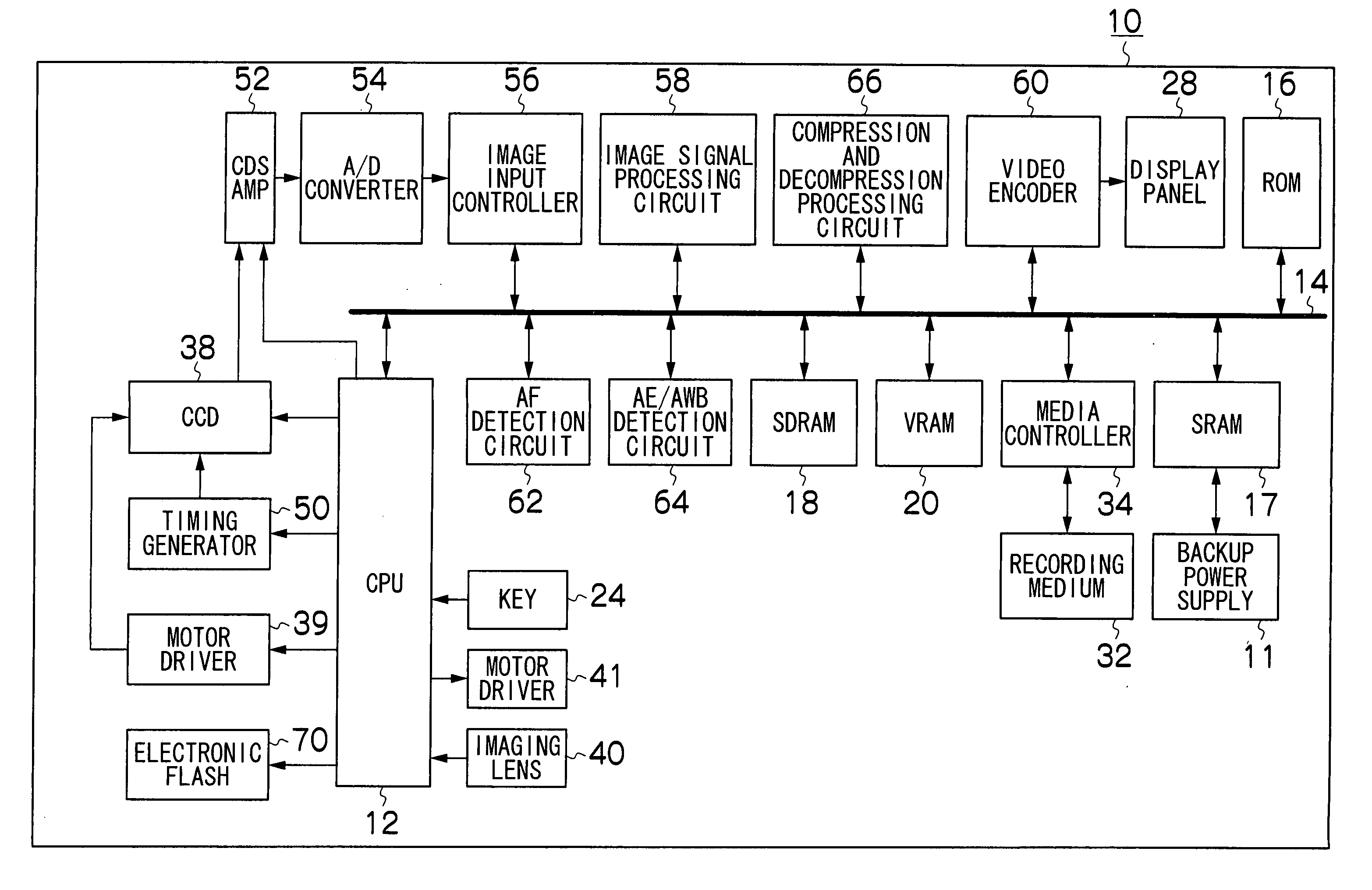
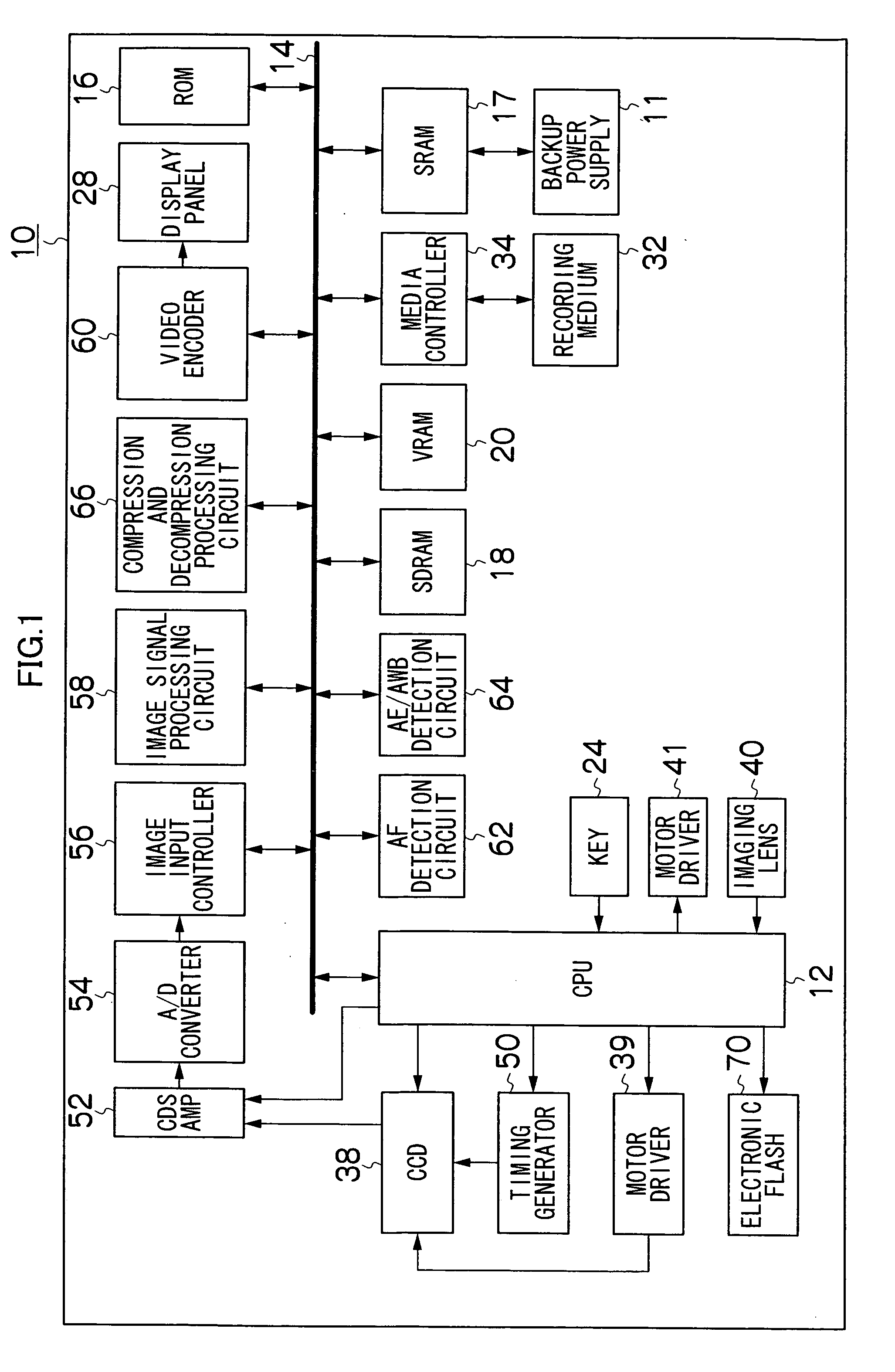
[0078]FIG. 1 is a block diagram showing the specific overall configuration of a camera10 as one embodiment of the imaging device of the present invention.

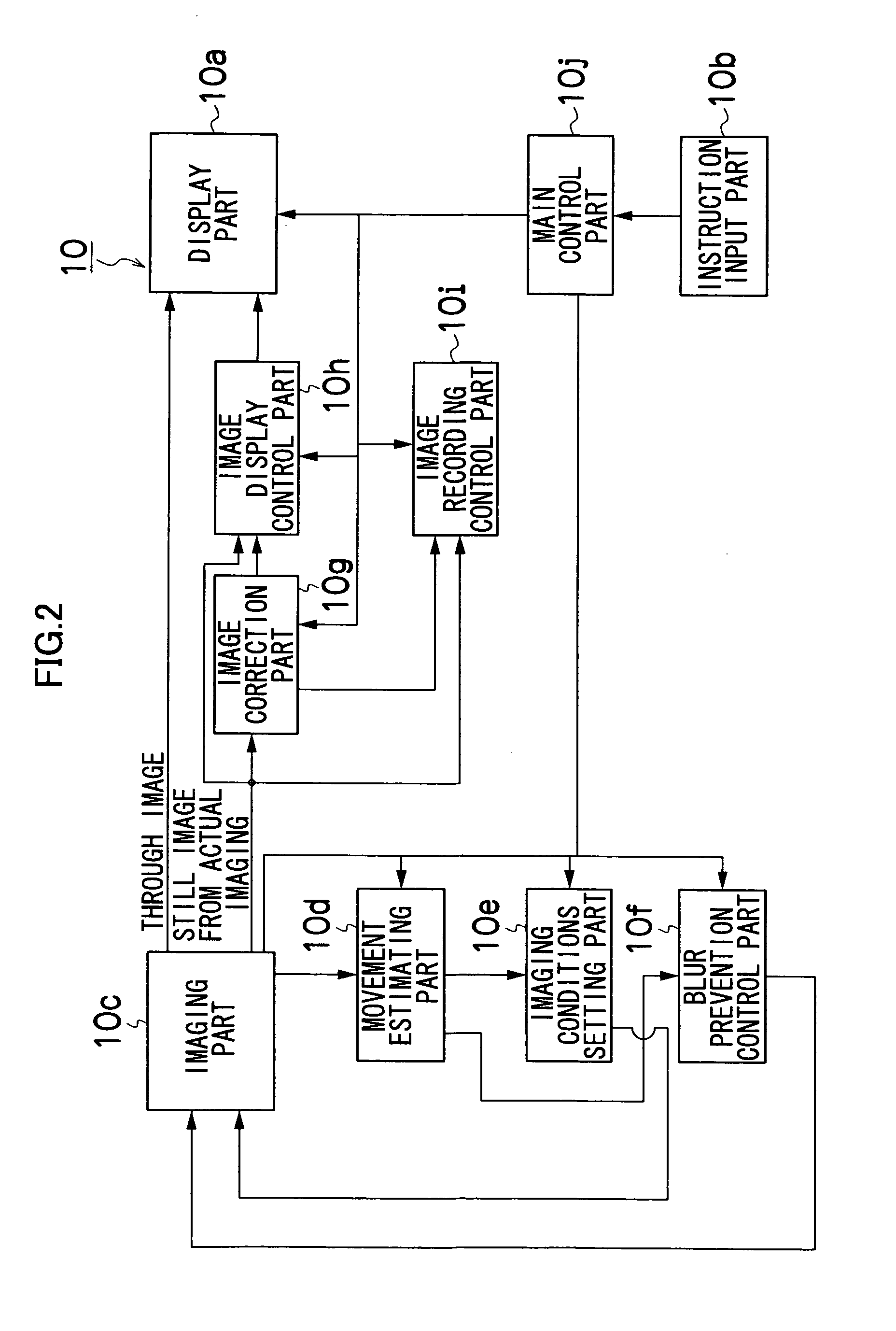
[0079] Centralized control of the camera 10 is performed by a central processing unit (CPU) 12. More specifically, the CPU 12 performs motion estimating processing that estimates the motion of the main subject and the camera 10, imaging conditions setting processing that sets imaging conditions for the camera 10, image correction processing that corrects images that were imaged, image display control processing that controls the display of imaged images, image recording control processing that controls recording of imaged images, as well as other kinds of control processing. A detailed description of these types of control processing is given below.

[0080] A ROM 16 that was connected to the ...


PUM


Abstract

An imaging device, comprising: an image pickup device which images a subject; and a motion estimating device which estimates a motion of the subject and a motion of the imaging device based on a dynamic image or a plurality of still images which are imaged to include the subject prior to actual imaging of a still image of the subject by the image pickup device.

Description

BACKGROUND OF THE INVENTION [0001] 1. Field of the Invention [0002] The present invention relates to an imaging device and an imaging method, and more particularly to an imaging device and imaging method that can prevent deterioration in the image quality of a still image captured in actual imaging that is caused by motion of the subject or motion of the imaging device. [0003] 2. Description of the Related Art [0004] In general, when imaging a subject in a state in which the subject is moving or the camera is moving, so-called subject blur or camera blur (also called camera shake) occurs within the image and deteriorates the image quality. [0005] Consequently, imaging devices have been proposed which have various measures taken to prevent blurs from occurring in images. [0006] Japanese Patent Application Laid-Open No. 2001-045340 discloses a device that by comparing imaging environment characteristics such as focus distance characteristics, exposure characteristics and color charact...

Claims


Application Information

Patent Timeline
IPC IPC(8): G03G15/00
CPCH04N5/23248H04N5/23254H04N5/23258H04N5/23264H04N23/6811H04N23/68H04N23/682H04N23/6812
Inventor NAKAMARU, FUMIO
Owner FUJIFILM CORP
Learn More