Fail-over storage system

a storage system and failover technology, applied in the field of failover storage systems, can solve the problems of increasing system management costs, not providing for a storage system capable of connecting multiple network domains, and failover processing executables in that configuration, so as to reduce system management costs

Inactive Publication Date: 2006-06-01
HITACHI LTD
View PDF15 Cites 107 Cited by
  • Summary
  • Abstract
  • Description
  • Claims
  • Application Information

AI Technical Summary

Benefits of technology

[0009] Usually, the conventional NAS storage system is composed of a file server and a storage system with the file server attached to a storage system as a host computer. The conventional fail-over technique considers a failure that might occur in the file server of the NAS storage system., but it does not consider any failure that might occur in the storage system of the NAS. Furthermore, the conventional fail-over technique gives no consideration to any failure that might occur in the storage system that performs the fail-over processing (resistance to multiple failures). In addition, the conventional technique does not provide for a storage system capable of connecting multiple network domains, nor to the fail-over processing executable in that configuration. Under the circumstances, one feature of the present invention is to provide a storage system that can reduce system management cost by managing numerous system interfaces collectively. In addition, the present invention provides a storage system resistant to multiple failures and capable of connecting many network domains.

Problems solved by technology

Consequently, each of those storage systems needs to be managed individually, increasing the system management cost.
Furthermore, the conventional fail-over technique gives no consideration to any failure that might occur in the storage system that performs the fail-over processing (resistance to multiple failures).
In addition, the conventional technique does not provide for a storage system capable of connecting multiple network domains, nor to the fail-over processing executable in that configuration.

Method used


Image

  • Fail-over storage system
  • Fail-over storage system
  • Fail-over storage system

Examples


Embodiment Construction

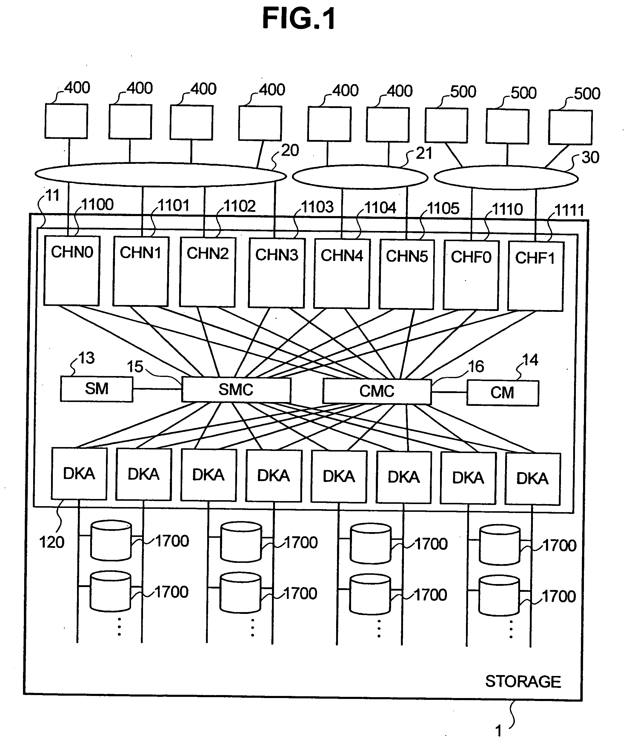
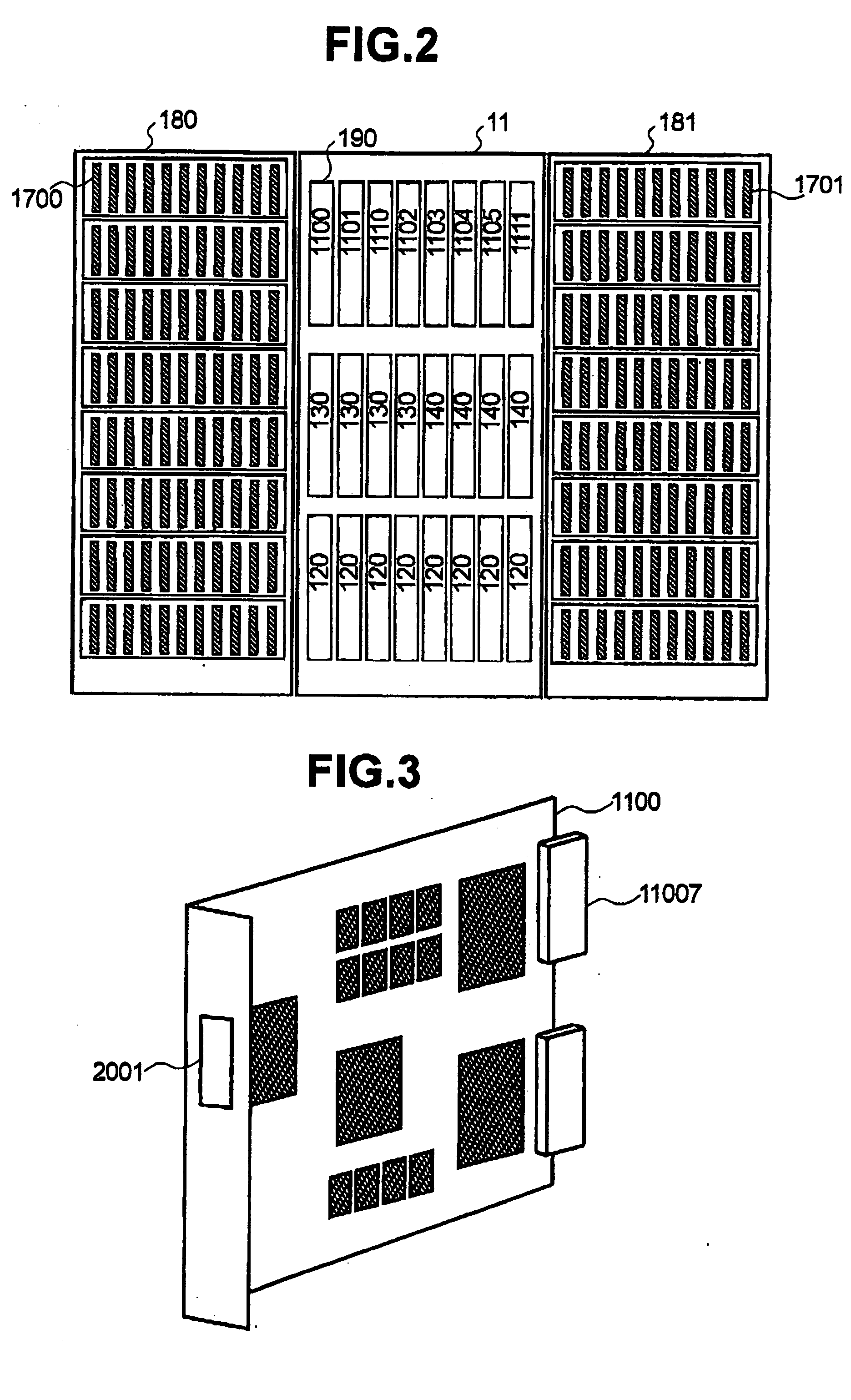
[0024] In a preferred embodiment of the present invention, each of the interface controllers is mounted as a board in the subject computer system and the shapes of all the controllers are the same so that they can be loaded in any of the slots. Furthermore, the above configuration of the storage system of the present invention, in another preferred embodiment, further includes a management table that manages fail-over interface controllers collectively, an information table that directs a fail-over procedure, and fail-over control means the taking-over of processing between interface controllers belonging to the same fail-over interface group according to the directed fail-over procedure.

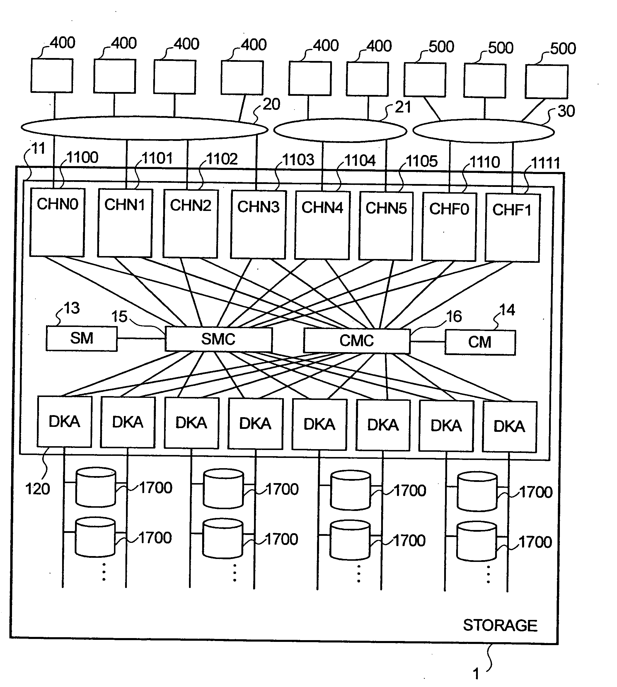
[0025]FIG. 1 shows an embodiment of a storage system of the present invention. (Herein, “x” denotes an integer.) Storage system 1 includes a disk controller 11 and multiple storage units 1700. In the disk controller 11, NAS channel adapters (CHN) 1100-1105, are interface controllers connected to NA...


PUM


Abstract

A storage system 1 including multiple slots for loading a block I / O interface controller, a file I / O interface controller, and any other kinds of interface controllers that are combined freely. The storage system 1 includes a management table that manages fail-over-enabled devices by grouping those devices in accordance with the interface type and the domain to which each device belongs; an information table that directs a fail-over procedure; and fail-over controlling means that takes over the processing of a failed interface controller belonging to a fail-over-enabled group. The fail-over system offers several modalities for monitoring failures, selecting takeover controllers and restoring functionality. Storage system 1 solves conventional problems by providing a system that can mount a plurality of file systems, and that resists multiple failures detected in a fail-over server.

Description

CROSS-REFERENCES TO RELATED APPLICATIONS [0001] The present application is a Continuation Application of U.S. application Ser. No. 10 / 150,245, filed May 15, 2002, which in turn is related to and claims priority from Japanese Patent Application No. 2002-006873, filed Jan. 16, 2002, both of which are incorporated by reference herein in their entirety for all purposes.BACKGROUND OF THE INVENTION [0002] 1. Field of the Invention [0003] The present invention relates to fail-over storage systems employed for computer systems. More particularly, the present invention relates to fail-over storage systems provided with a plurality of input / output interfaces. [0004] 2. Background of the Invention [0005] Interfaces (I / F) used between storage systems and computers are roughly classified into two types. The first type is the “block I / O interface.” This interface enables data input / output (I / O) in blocks, a block being a unit of data management of storage units. The fiber channel, the SCSI (Small...

Claims


Application Information

Patent Timeline
Patent Type & Authority Applications(United States)
IPC IPC(8): G06F11/00G06F3/06G06F11/20G06F13/00H02H3/05
CPCG06F11/0727G06F11/0766G06F11/2025G06F11/2033G06F11/2043G06F11/2069G06F11/2092
Inventor MATSUNAMI, NAOTOSONODA, KOUJIKITAMURA, MANABUOEDA, TAKASHITAKATA, YUTAKA
Owner HITACHI LTD
Why Eureka
Try Eureka