Electric phase bus bar

a technology of electric phase bus and bus bar, which is applied in the direction of electrical equipment, connections, arrangement with metal casings, etc., can solve the problem of curved section that is not suitable for bolting connections

Inactive Publication Date: 2006-06-08
SIEMENS CORP
View PDF14 Cites 21 Cited by
  • Summary
  • Abstract
  • Description
  • Claims
  • Application Information

AI Technical Summary

Problems solved by technology

The U-shaped bus channel typically has a curved section that is not suitable for bolting connections within the switchgear enclosure.

Method used


Image

  • Electric phase bus bar
  • Electric phase bus bar
  • Electric phase bus bar

Examples


Embodiment Construction

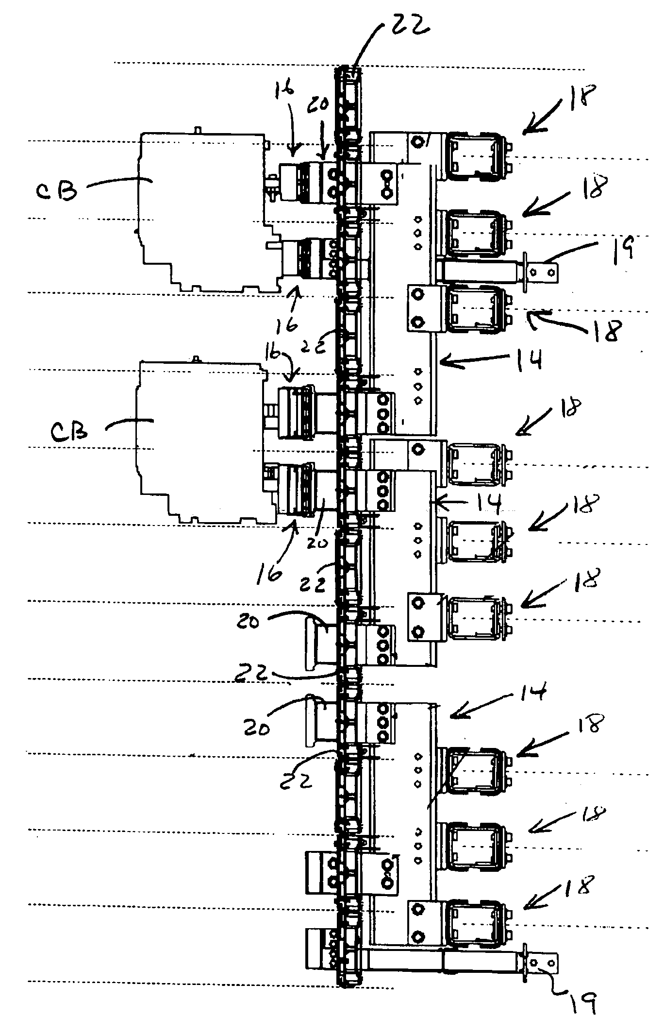
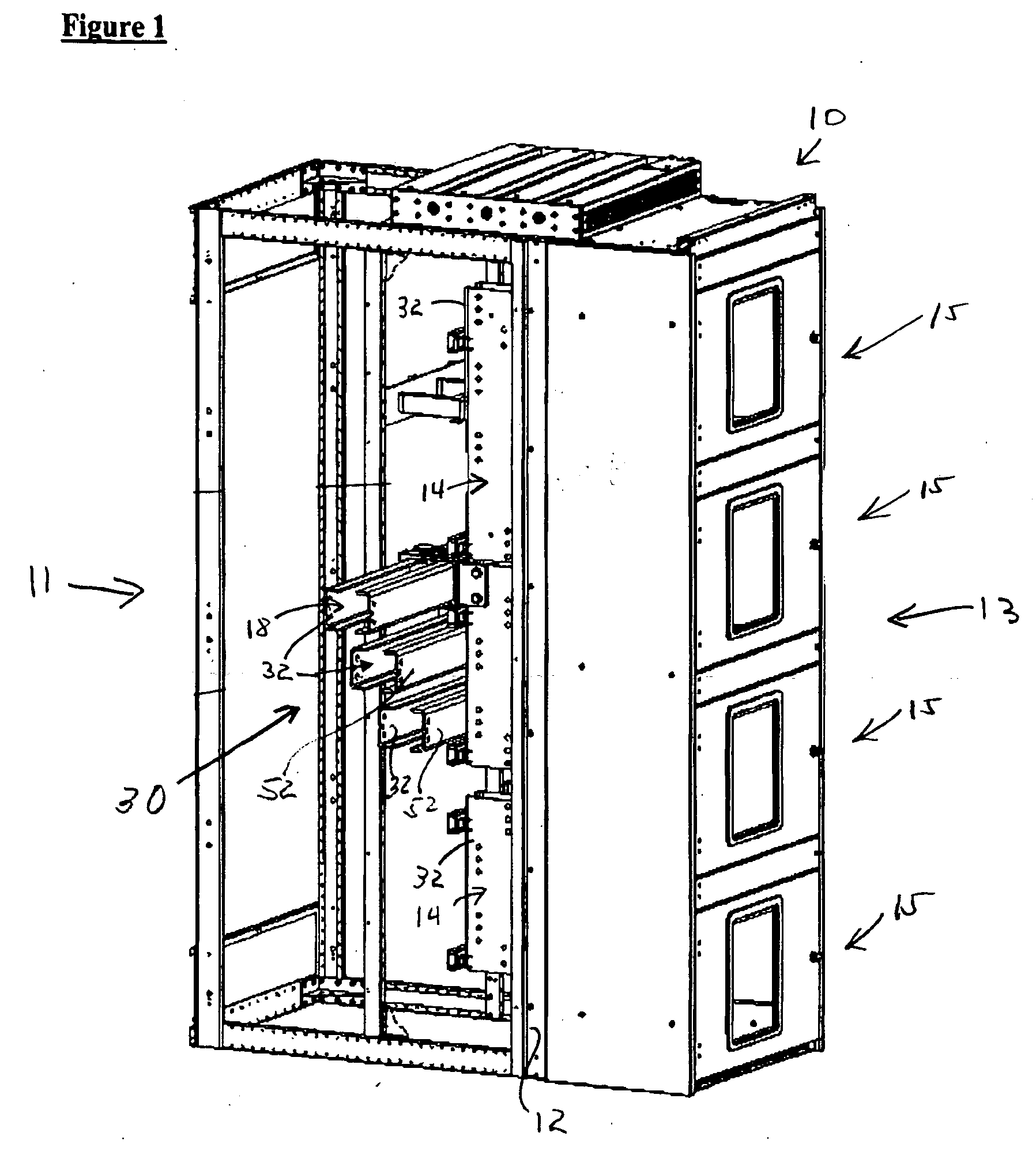
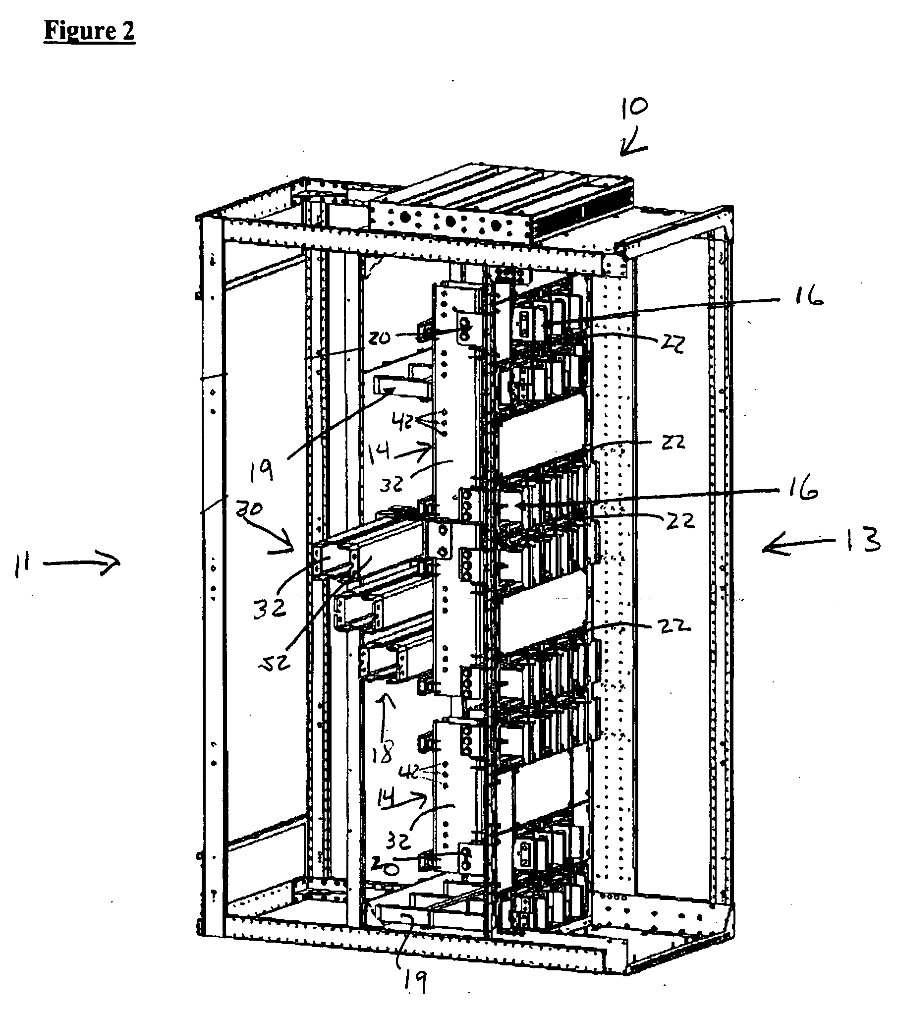
[0018] Before describing the exemplary embodiments of an electrical bus bar system for electrical equipment in a switchgear enclosure, several comments are appropriate. Switchgear assemblies and panel board assemblies typically include vertical (section) bus bars to distribute electrical power within the enclosures. In a short circuit condition, extreme magnetic forces are created in the bus bars as a result of short circuit currents up to and including 200,000 amps symmetrical RMS flowing through each bus bar. In a three phase power system (typically) a short circuit current flows through such bus bars with magnetic forces between adjacent bus bars tending to move such bus bars laterally (perpendicular) to the current flow. Such movement of the bus bars are typically prohibited or inhibited to avoid damage in arcing with switchgear enclosures by bus bar brace apparatus and equipment arrangements within the switchgear cabinet.

[0019] In order to improve the section modulus for high ...


PUM


Abstract

A method and an electric bus bar in an electrical enclosure. The electrical bus bar includes a web portion having a first side and a second side. A pair of flanges are formed with one flange on each side of the web portion and positioned perpendicular to the web portion. The sum of the lengths of both flanges is less than the width of the web portion.

Description

FIELD [0001] The present invention relates generally to the field of electrical switchboards and panel boards and more particularly to an electric bus bar in switchboard and panel board enclosures, where the sum of the length of the bus bar flanges is less than the width of the bus bar web portion. BACKGROUND [0002] Switchgear assemblies and switchboards and panel boards are general terms which cover metal enclosures, housing switching and interrupting devices such as fuses and circuit breakers, along with associated control, instrumentation and metering devices. Such assemblies typically include associated bus bars, interconnections and supporting structures used for the distribution of electrical power. Low voltage switchgear and switchboards operate at voltages of up to 600 volts and with continuous currents up to 5000 amps or higher. Such devices are also designed to withstand short circuit currents ranging up to 200,000 amps (3 phase RMS symmetrical). [0003] Typical switchgear ...

Claims


Application Information

Patent Timeline
Patent Type & Authority Applications(United States)
IPC IPC(8): H01R9/22
CPCH02B1/20H02B13/02
Inventor JOSTEN, HARRY W.WIANT, JASON P.
Owner SIEMENS CORP
Why Eureka
Try Eureka