Device for positioning a bone cutting guide

a technology for positioning devices and cutting guides, which is applied in the field of devices for positioning cutting guides, can solve the problems of invasiveness for patients, unnecessary damage to the bone, and the size of devices in the vicinity of the bone,

Active Publication Date: 2006-06-08
OMNILIFE SCI INC
View PDF14 Cites 153 Cited by
  • Summary
  • Abstract
  • Description
  • Claims
  • Application Information

AI Technical Summary

Benefits of technology

[0013] The present invention aims at providing a positioning device for positioning a cutting guide relative to a bone that does not require a base element or anchor to be first fixed to the bone.

Problems solved by technology

In particular, for knee joint replacements, it is very important that the implants be well positioned on and well oriented to each bone, because deviations of 2 mm or 2° can jeopardize the success of the operation.
The main disadvantage of the previously described positioning devices is that they rely on an anchoring member or a base component which must be first fixed to the bone, and a number of positioning elements that connect the cutting guide to the base for adjusting the angle and / or the position of the cutting guide relative to the base with a least 1 and up to 6 degrees of freedom.
These types of devices therefore usually take up considerable space in the vicinity of the bone and are invasive for the patient.
Moreover, since an anchoring member or a base component is first fixed to the bone, such positioning devices lead to unnecessary damages of the bone.
Besides, such positioning devices are usually time consuming to install.

Method used


Image

  • Device for positioning a bone cutting guide
  • Device for positioning a bone cutting guide
  • Device for positioning a bone cutting guide

Examples


second embodiment

[0043] In the present invention, the contact between the cutting guide and the bone is shared between at least 2 adjustable bone contact surfaces and at least one non adjustable contact surface which is integral to or rigidly fixed to the cutting guide. In this embodiment, the system provides at least one mechanical constraint to assure that the guide is positioned in a specific manner with respect to the bone. This positioning constraint preferably complies with some surgical criteria, such as, for example, preventing notching of the anterior femoral cut, or specifying a fixed cutting depth as referenced from one of the distal condyles at the end of the bone. Optionally, additional mechanical constraints can be provided to stabilize the cutting guide relative to the bone.

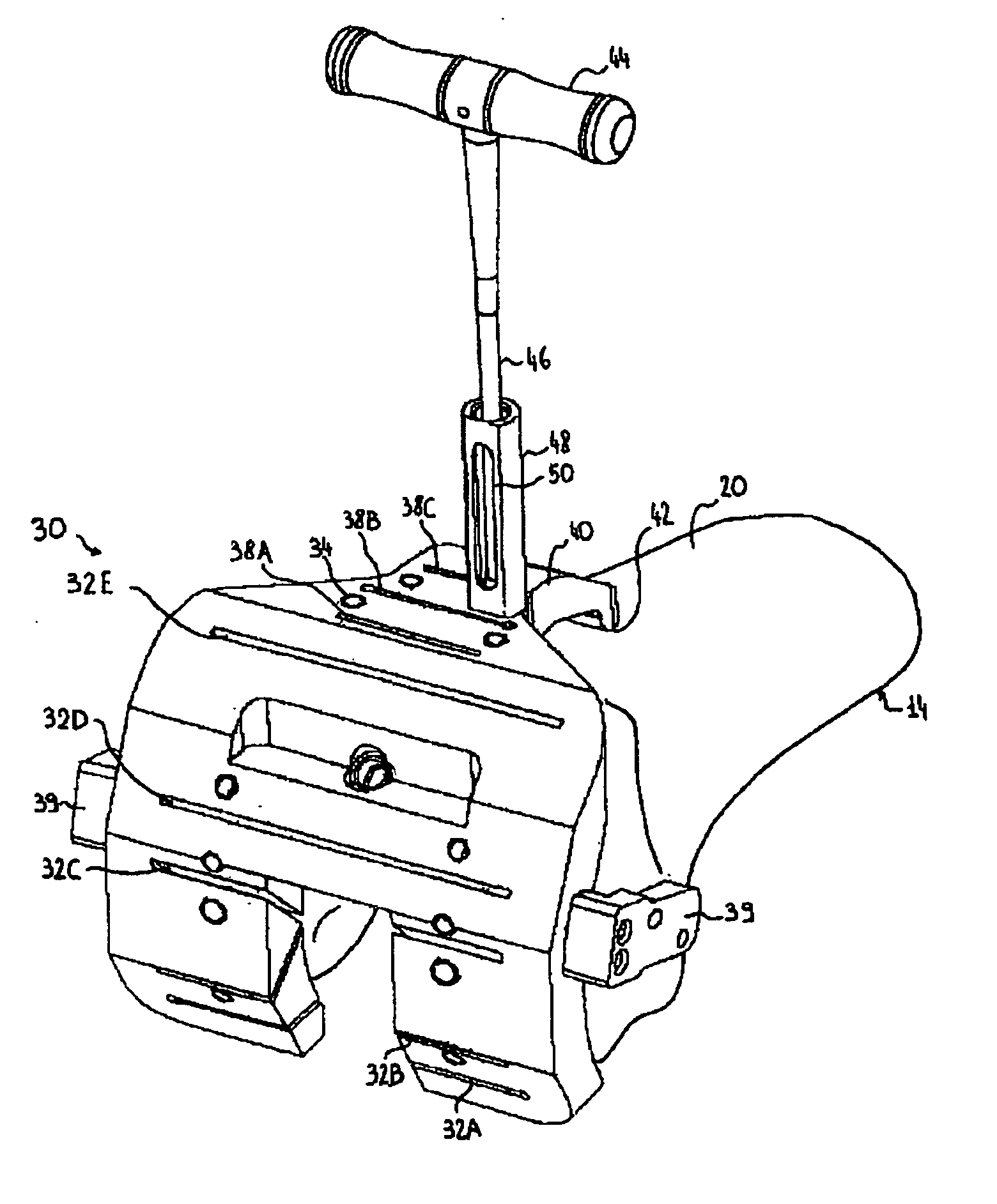
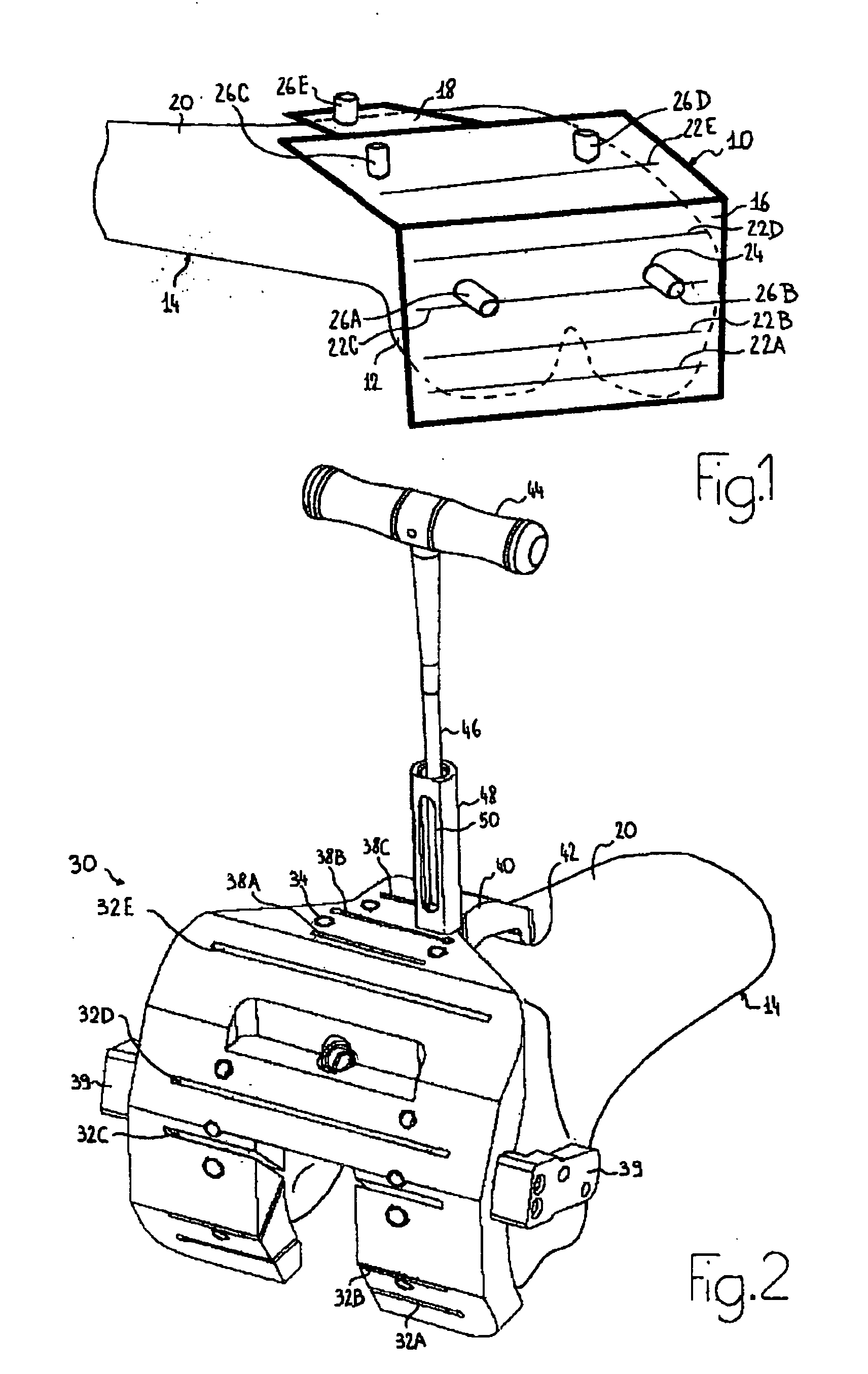
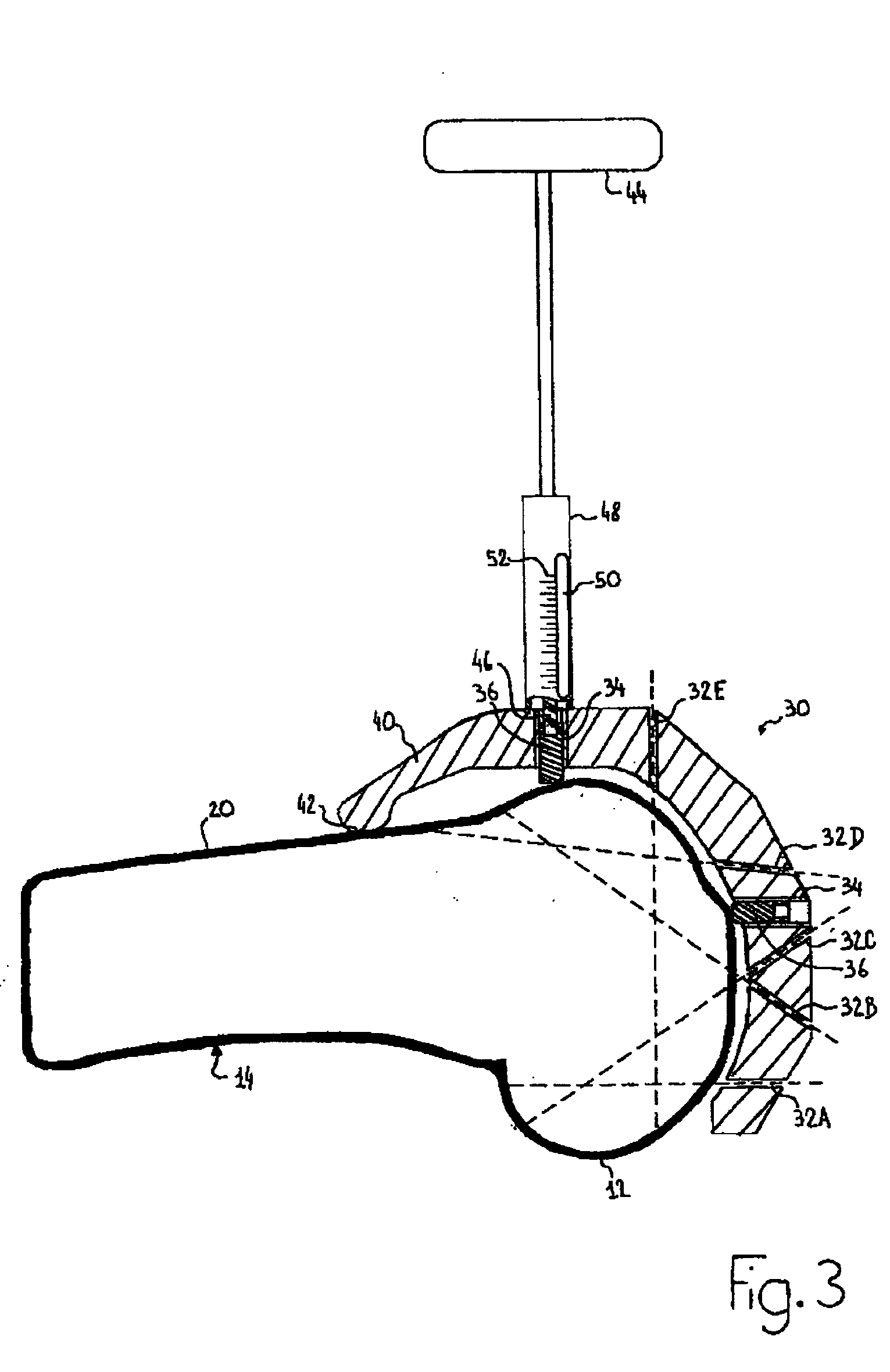
[0044]FIGS. 2 and 3 show an example of a cutting guide 30 according to such a second embodiment, still in relation to knee replacement surgery. In contrast with the first embodiment, the guide positioning system do...

third embodiment

[0058] the present invention will now be described wherein at least some of the adjustment screws are attached to an intermediate member which is temporarily fixed to the cutting guide.

[0059]FIG. 6 shows such an intermediate member 90 which comprises four threaded holes 92 receiving four screws 94A-94D. This intermediate member 90 is adapted to cooperate with a cutting guide, not shown on FIG. 6, having the general shape illustrated on FIGS. 1 or 2. The intermediate member 90 includes a hole 96 to be located opposite to a threaded hole of the cutting guide in order to fix the intermediate member 90 to the cutting guide by use of a screw. As an alternative, the intermediate member comprises a quick release clip cooperating with a corresponding clip provided on the cutting guide so that the intermediate member can be quickly removed after the cutting guide is positioned and fixed to the bone. The intermediate member 90 includes an extending portion 98 for attaching a rigid body, not s...

fourth embodiment

[0062]FIG. 8 shows a cutting guide 110 aimed to be positioned at the end of a tibia or a femur, for making a single cut such as the proximal tibial cut or the distal femoral cut. Such a cutting guide comprises a parallelepiped body 112 which includes at least one cutting surface or slot, not shown, for the realization of at least the single cut. The cutting guide 110 includes two curved arms 114A, 114B. A curved arm 114A, 114B continues with a cylindrical portion 116A, 116B of parallel axis, the tip of which corresponds to a contact surface 117A, 117B. The displacement of an arm 114A, 114B along the direction of the axis of the cylindrical portion 116A, 116B is obtained by means of an actuation mechanism 118A, 118B similar to the translational and rotational actuation mechanisms previously described above. The cutting guide 110 also includes a threaded hole 120 receiving a screw 122 the tip of which corresponds to a contact surface 124. The actuation of the screw 122 and the actuati...


PUM


Abstract

A device for positioning a cutting guide with respect to a bone comprising a body forming the cutting guide or intended to be fixed to the cutting guide; a least two contact members intended to freely contact the bone; and adjustment means for individually varying the relative position of the body with respect to each contact member.

Description

BACKGROUND OF THE INVENTION [0001] 1. Field of the Invention [0002] The present invention relates to a device for positioning a cutting guide relative to a bone. It applies to orthopaedic surgical procedures such as, for example, joint replacement surgery. [0003] 2. Discussion of the Related Art [0004] In joint replacement operations, it is often required that portions of the ends of the bones of the joint be resected and replaced with endoprosthetic implants. In particular, for knee joint replacements, it is very important that the implants be well positioned on and well oriented to each bone, because deviations of 2 mm or 2° can jeopardize the success of the operation. [0005] In order to cut the bones in a specific cutting plane, a surgeon commonly uses a cutting guide which includes a flat or slotted surface for guiding a saw blade in the cutting plane. Some cutting guides allow the guiding of the saw blade in several different cutting planes. For example, some cutting guides def...

Claims


Application Information

Patent Timeline
Patent Type & Authority Applications(United States)
IPC IPC(8): A61F5/00
CPCA61B17/155A61B17/157A61B17/1764A61B17/15A61B19/54A61B2019/505A61B2019/508A61B19/5244A61B34/20A61B2034/105A61B2034/108A61B90/39
Inventor LAVALLEE, STEPHANEBERTRAND, FABRICEBOYER, ANTHONYPLASKOS, CHRISTOPHER
Owner OMNILIFE SCI INC
Why Eureka
Try Eureka