
Shipping and display tray

Inactive Publication Date: 2006-06-15
INT PAPER CO
View PDF10 Cites 24 Cited by
  • Summary
  • Abstract
  • Description
  • Claims
  • Application Information

AI Technical Summary

Benefits of technology

[0007] The present invention is a container or tray for shipping and displaying product at a point of sale, wherein the tray has good stacking strength, can be stacked without nesting or telescoping into one another, provides good visibility of and access to the product, does not require the removal of a separate reinforcing divider panel in order to access the product, and wherein the product can be removed from the back of the tray through the front without having to lift the product.
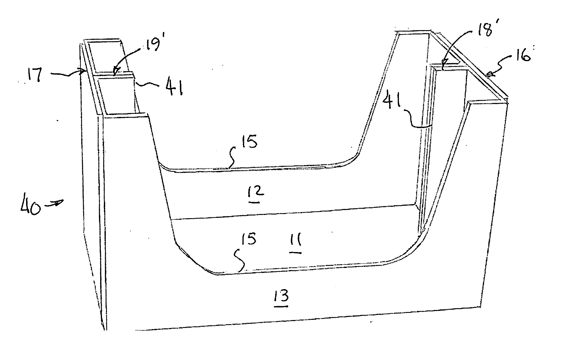
[0008] To accomplish the foregoing, the shipping and display tray of the invention comprises a bottom wall, opposite sidewalls that are cut down to provide visibility of and access to the product, opposite end walls, an open top, and reinforcing panels that are left in place during use of the tray and that provide visibility of and easy access to all the product from either side of the tray. The reinforcing panels extend the full height of the tray at its ends to prevent nesting of the trays when they are stacked, but extend inwardly from the middle of the opposite end walls only a relatively short distance, leaving a space or opening between the reinforcing panels through which product may be withdrawn from the back of the tray and through the front without having to lift the product. The end walls of the tray extend the full height of the tray and are of double thickness, and the reinforcing panels define two additional corners in each end of the tray, significantly increasing the strength of the tray. A tray in accordance with the invention can provide a top to bottom compression strength of 2,000 pounds.
[0009] In one form of the invention, the tray is constructed from a single unitary blank of corrugated paperboard, and is designed so that it can be produced on high-speed machinery. The blank includes a bottom-forming panel, opposite end wall panels, opposite sidewall panels, and extensions on opposite ends of the sidewall panels that form end wall flaps and reinforcing divider panels. In a tray erected from the blank, the end wall flaps each extend the full height of the tray and half way across its width and are glued to the inside of the end wall panels. The reinforcing divider panels also extend the full height of the tray, and extend inwardly a short distance from each end wall along the longitudinal centerline of the tray and are glued together. Both sidewalls are cut down or recessed over most of their height and length, providing large openings in the sides of the tray through which the product is visible and accessible. The narrow reinforcing divider panels provide a large opening between them through which product is visible and easily accessible from either side of the tray.
[0012] Moreover, the divider panels can extend into the tray a relatively short distance, e.g., about two inches, providing clearance for machinery to apply plastic handles to pairs of the product containers held in the tray. The embodiment shown in FIGS. 9-13 has these relatively narrow divider panels.

Problems solved by technology

The consumer is then frequently left with the task of removing the divider panels, and / or sale of the product may be discouraged if the divider panel is left in place and the product is not readily visible and accessible.
This, obviously, is not possible or practical when containers are stacked on top of one another.
In other containers of this type, the divider is omitted in the center portion of the tray, whereby product does not have to be lifted in order to remove it from the container, but the end walls of the tray do not extend the full height of the container, thus reducing the strength of the container.

Method used


Image

  • Shipping and display tray
  • Shipping and display tray
  • Shipping and display tray

Examples


first embodiment

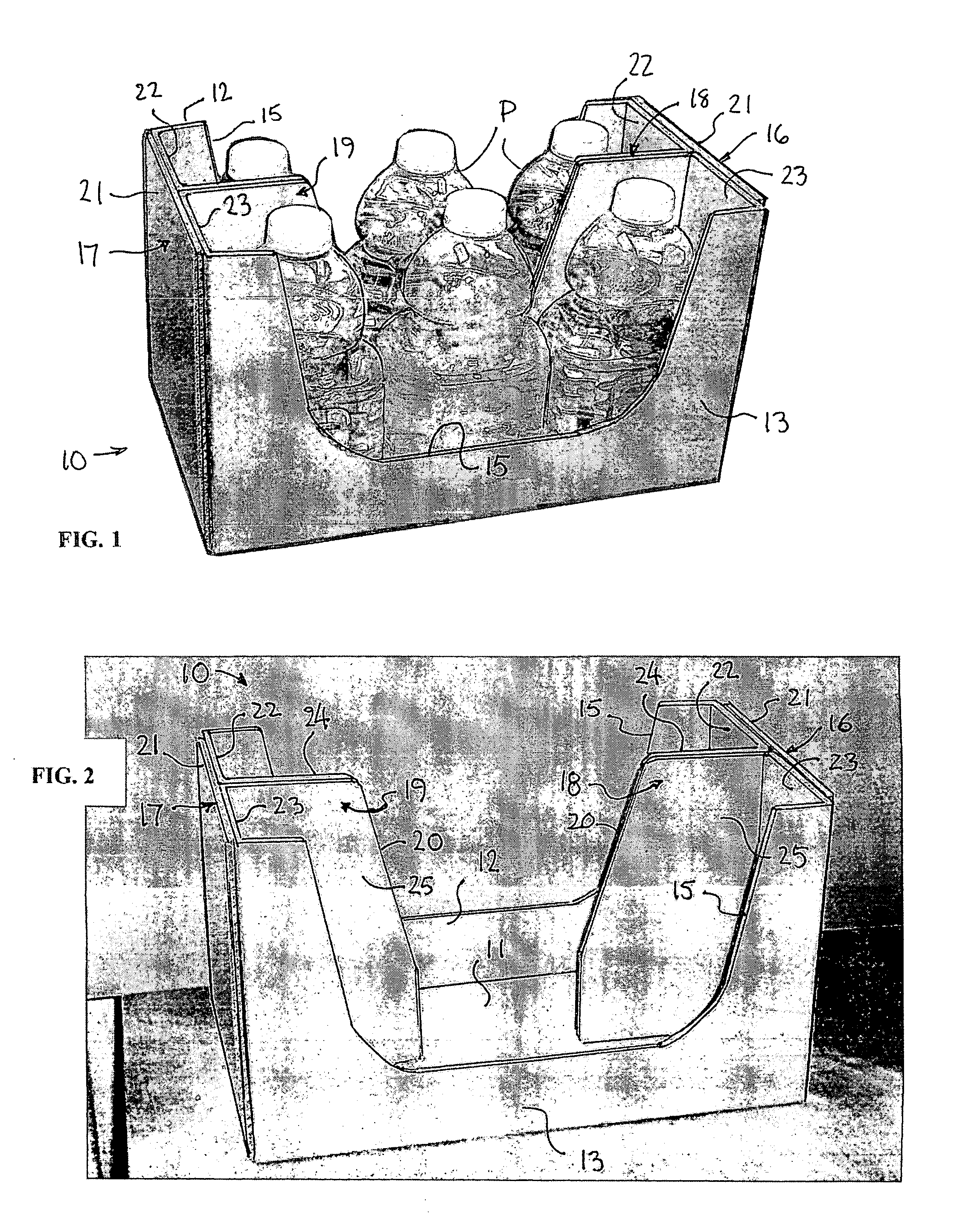
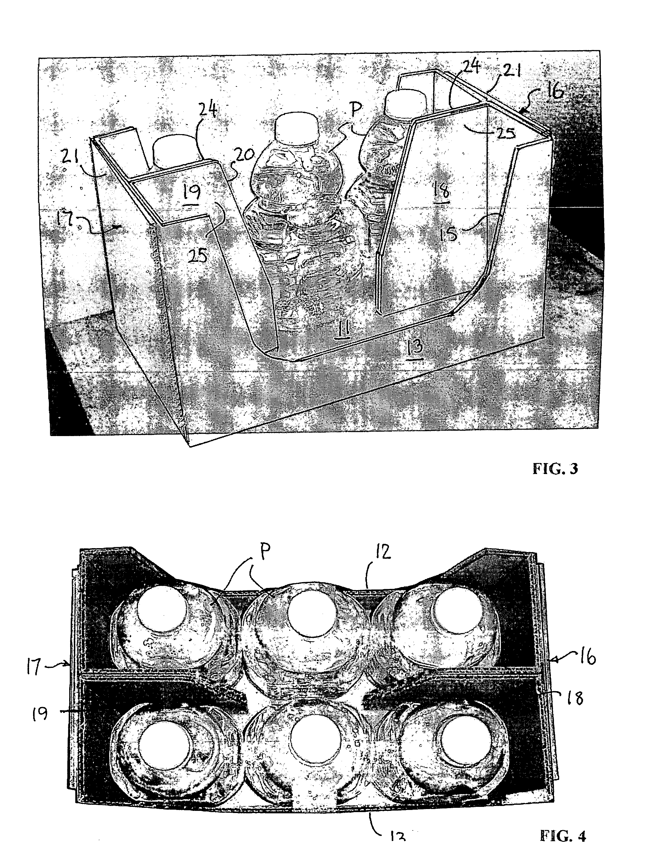
[0029] the tray according to the invention is represented generally at 10 in FIGS. 1-4. The tray comprises a tray bottom portion having a bottom wall 11, opposite side walls 12 and 13 with large cut-out areas 15, and opposite end walls 16 and 17, and reinforcing divider panels 18 and 19 extending a short distance inwardly of the tray toward one another from the middle of the end walls. In this embodiment, each divider panel extends over approximately one-third the length of the tray, and has a sloping inner edge 20 so that the panels are narrower at their top than at their bottom.

[0030] The end walls each comprise an outer end wall panel 21 folded upwardly from opposite end edges of the tray bottom wall, and end wall flaps 22 and 23 extending inwardly from opposite ends of the respective side walls. The end wall flaps each extend approximately one half the width of the respective end wall, and lie inside the end wall panels and are glued thereto. The end wall panels and end wall fla...


PUM


Abstract

A tray (10, 40, or 50) for shipping, displaying and vending containers of product has side walls (12, 13 or 12′, 13′), end walls (16, 17 or 16′, 17′), an open top, and a bottom wall (11). The sidewalls have an open center portion (15) through which product (P) held in the tray is easily visible and accessible for removal from the tray. The end walls have first and second laminated end wall panels (21 and 22, 23, or 57, 58 and 70, 71), and in one embodiment the sidewalls have laminated sidewall flaps (59, 60 and 62, 63), forming double-wall constructions. A full-height reinforcing divider (18, 19 or 18″, 19″) extends vertically along an inner surface of each end wall substantially midway of the width thereof to reinforce the tray and prevent it from telescoping into another tray when they are stacked. The dividers at opposite ends of the tray are spaced from one another, defining a large opening between them through which product may be removed through the front from the back of the tray without having to lift the product, whereby product can be removed from the back of the tray through the front when multiple trays are stacked on top of one another.

Description

[0001] This application claims the benefit of U.S. provisional patent application Ser. No. 60 / 636,086, filed Dec. 14, 2004.TECHNICAL FIELD [0002] This invention relates to containers, and more particularly to a tray for shipping and displaying consumer products. BACKGROUND ART [0003] Many consumer products are shipped from a manufacturer or distributor to a point of sale in containers that permit the product to be left in the container and displayed at the point of sale. This is especially true of products displayed and sold in large warehouse or club-type stores, wherein the product is commonly left in the shipping container. These containers must have sufficient strength to stack them on top of one another and to withstand handling, and they also desirably are constructed so that the product can be easily seen while it remains in the container. Easy access to and removal of the product from the container by a consumer is also a desirable feature. [0004] Some prior art containers m...

Claims


Application Information

Patent Timeline
IPC IPC(8): B65D5/00B65D25/04
CPCB65D5/445
Inventor WEIMER, CHARLES P. JR.
Owner INT PAPER CO
Learn More