Image display method and image display apparatus

a technology of image display and display method, which is applied in the field of image display apparatus, can solve the problems of reducing image quality, increasing scanning frequency, and becoming difficult to cope with the increase in display frequency associated with the increase in density, and achieves the effect of eliminating information of the lower recognition level and high speed

Inactive Publication Date: 2006-06-15
HIYAMA IKUO +7
View PDF11 Cites 12 Cited by
  • Summary
  • Abstract
  • Description
  • Claims
  • Application Information

AI Technical Summary

Benefits of technology

[0015] It is a first object of the present invention to provide a display method which can achieve both a substantially high definition image display and high speed dynamic image display by eliminating information of lower recognition level utilizing visual characteristics for still image display and dynamic image display.
[0016] It is a second object of the present invention to provide an image display apparatus which is capable of arbitrarily switching between a region for lowering definition of a dynamic image and displaying with rewriting at high speed, and a region of high definition display of a still image when rewriting at low speed.
[0017] It is a third object of the present invention to provide an image display system constructed with image generating means, display control means, information storage means, and dynamic image / still image judgment means for achieving both a high definition display and a high speed dynamic image display.

Problems solved by technology

However, in a current display method for display of an image or a current driving system for use in an image display apparatus, it is becoming difficult to cope with the increase in the display frequency associated with the increased density of the display due to signal delay on the line, lack of a sufficient writing period to respective pixels and an increase in the scanning frequency.
According to this report, due to mismatching of a dynamic image in hold illumination and the radial motion of the human eye when following a dynamic image, bluing of the dynamic image can be caused so as to lower the image quality of the dynamic image display.
However, as set forth above, in the current method of display of an image or the driving system used in the image display apparatus, the increasing of the display frequency is becoming close to the limit.
Furthermore, nothing has been mentioned in connection with a method capable of achieving both high definition and high speed display.
However, for dynamic image display, in which the entire screen image is rewritten, a high speed dynamic image display is difficult due to signal delay and a limitation on the writing performance.
However, there are lots of problems to be solved, such as reliability, stability, uniformity and so forth.
Therefore, it is estimated that it will require a long development period to obtain a satisfactory product.

Method used


Image

  • Image display method and image display apparatus
  • Image display method and image display apparatus
  • Image display method and image display apparatus

Examples


first embodiment

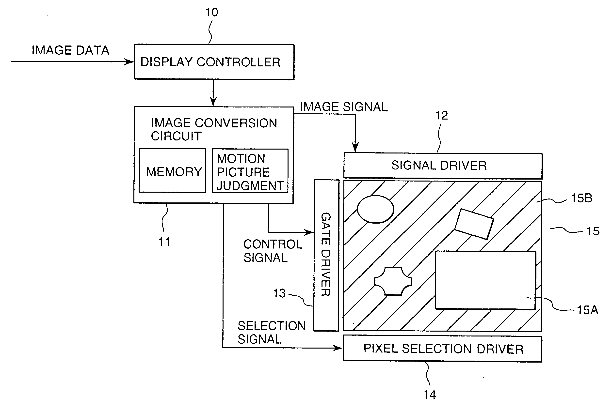
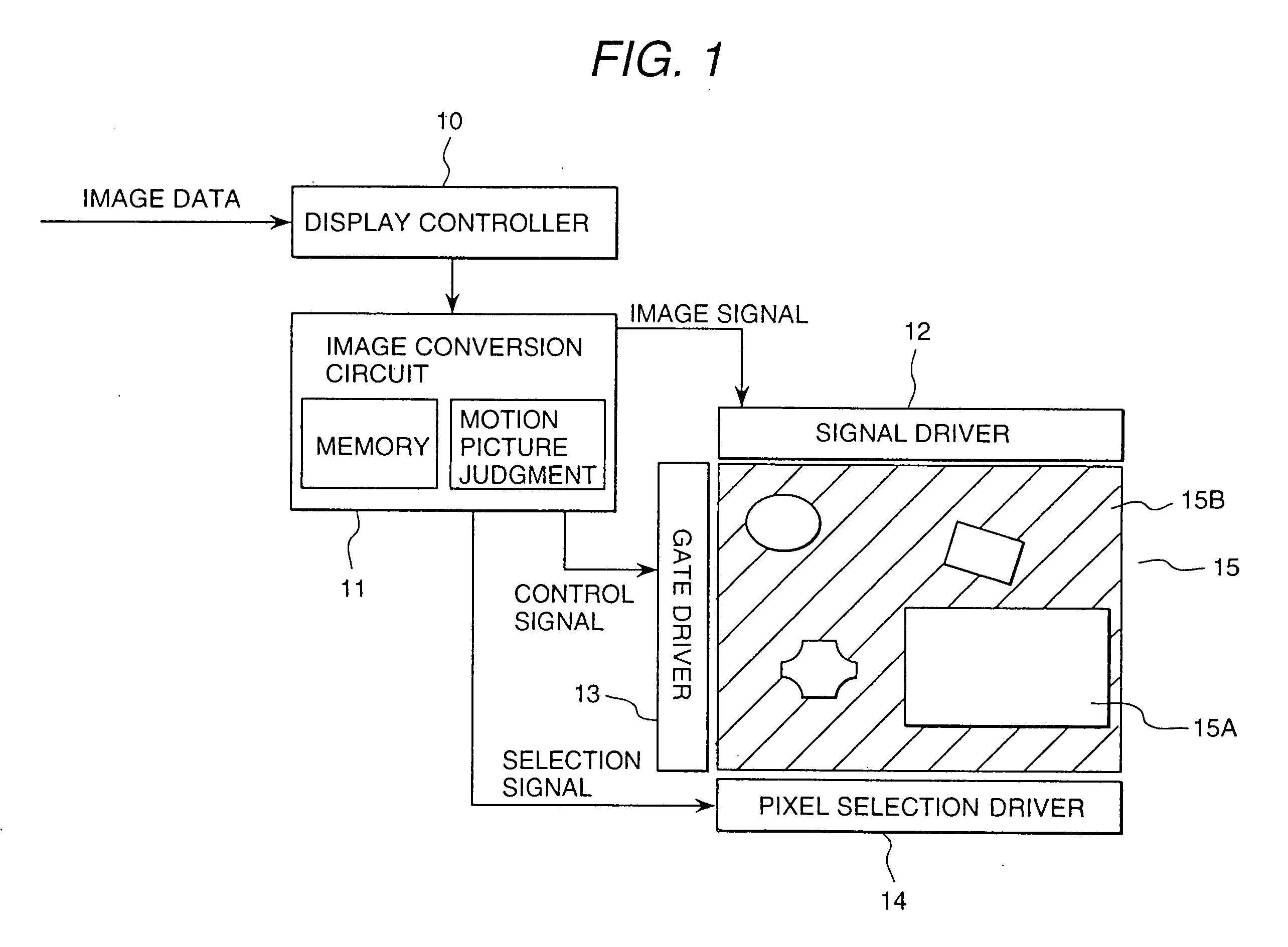
[0093]FIG. 3 is a circuit diagram showing an embodiment of a pixel circuit construction for realizing image zone separating display according to the present invention.

[0094] The first embodiment is directed to a pixel circuit construction taking a 2 pixels×2 pixels arrangement as one block. A plurality of such pixel circuit constructions are arranged for forming an overall display area of the display panel 15. It should be noted that one pixel block does not necessarily consist of four pixels, but can be any reasonable number. However, in consideration of a lowering of the opening ratio due to an increase in the number of lines and so forth, it is preferred to form one pixel block with four pixels.

[0095] It should be noted that the image display apparatus employing the image zone separating display system of the present invention is not only applicable for a liquid crystal display, but also may be applied to an ELD, FED, PDP and so forth. Here, the present invention will be discus...

second embodiment

[0113]FIG. 5 is a plan view of a pixel structure pattern for realizing an image zone separation display according to the present invention.

[0114] This second embodiment is provided with a pixel electrode and an opposed electrode on the same substrate and is a system for applying a lateral electric field to the liquid crystal layer. In this embodiment, an arrangement of 2×2 pixels are taken as one block unit. A plurality of block units are arranged for forming the entire display area. The number of pixels forming one block unit is not limited to four but can be any number. However, in consideration of a lowering of the opening ratio due to an increase in the number of lines and so forth, it is preferred to form one pixel block with four pixels.

[0115] It should be noted that an image display apparatus employing the image zone separating display system of the present invention is not only applicable to a liquid crystal display, but is also applicable to an ELD, FED, PDP and so forth....

third embodiment

[0124]FIG. 6 is a plane view of a third embodiment of the pixel structure pattern for realizing an image zone separation display according to the present invention. The third embodiment has a pixel electrode on one of a pair of transparent substrates and an opposed electrode on the other transparent substrate. A vertical electric field is applied the liquid crystal layer. In the third embodiment, a color filter has a stripe structure perpendicular to the scanning line 20.

[0125] The scanning line 20 which is provided in common for four pixels is formed at the center. To the scanning line 20, the gates of the thin film transistors 24AB, 24CB are connected. To drain electrodes of the thin film transistors 24AB and 24CB, operating as the first switches, block selection signal lines 21A and 21C are respectively connected by contact portions 27AB and 27CB.

[0126] To the source electrodes of the thin film transistors, operating as the first switch, gate electrodes of the thin film transis...


PUM

PropertyMeasurementUnit
rewriting speedaaaaaaaaaa
thicknessaaaaaaaaaa
weightaaaaaaaaaa

Abstract

A display method can achieve both a substantially high definition image display and high speed dynamic image display. The image displaying method of an image displaying apparatus having a display portion consisting of a plurality of pixels takes each of a predetermined number of pixels as one block unit and forms one screen image for display by combining a region for displaying the same information on a plurality of pixels in one block unit during one scanning period and a region for permitting display of respectively different information on the plurality of pixels in the one block unit.

Description

CROSS REFERENCE TO RELATED APPLICATION [0001] This application is a continuation of U.S. application Ser. No. 09 / 829,078, filed Aril 10, 2001, the contents of which are incorporated herein by reference.BACKGROUND OF THE INVENTION [0002] The present invention relates to an image display apparatus. More particularly, the invention relates to means for arbitrarily switching display resolution and rewriting speed of an image within a display screen. [0003] In recent years, progress has been made in the reduction of the thickness and weight of an image display apparatus. In place of the CRT which has been primarily used as an image display device, a flat panel display, such as a liquid crystal display, PDP (Plasma Display Panel), and ELD (Electroluminescent Display) has experienced widespread use. On the other hand, the development of new technology, such as the design of a FED (Field Emission Display) and so forth, has also received much attention. Furthermore, as a result of the widesp...

Claims


Application Information

Patent Timeline
Patent Type & Authority Applications(United States)
IPC IPC(8): G09G3/36G02F1/1335G02F1/133G02F1/13357G09G3/20H04N5/66
CPCG09G3/20G09G3/3659G09G2300/0439G09G2300/0814G09G2310/0262G09G2310/06G09G2340/0407
Inventor HIYAMA, IKUOKOMURA, SHINICHIYAMAMOTO, TSUNENORIAOYAMA, TETSUYASATO, HIDEOTSUMURA, MAKOTOKONDO, KATSUMIUTSUMI, YUKA
Owner HIYAMA IKUO
Why Eureka
Try Eureka