
Optical lens assembly for a handheld electronic device

a handheld electronic device and optical lens technology, applied in the direction of color television details, television systems, instruments, etc., can solve the problems of significant differences, difficult to come up with small-sized optical lens assemblies for use in handheld devices such as mobile phones, and difficult to improve the performance of lens assemblies

Inactive Publication Date: 2006-06-22
MAXFORD TECH LTD
View PDF8 Cites 5 Cited by
  • Summary
  • Abstract
  • Description
  • Claims
  • Application Information

AI Technical Summary

Benefits of technology

[0007] According to a first aspect of the present invention, there is provided an optical lens assembly including at least one light-sensitive member; at least first and second lenses / lens groups with their respective optical axis aligned with each other along a common optical axis; and at least first and second piezo electric ultrasonic linear motors; wherein said first motor is operable to move said first and second lenses / lens groups relative to each other to vary the distance therebetween; and wherein said second motor is operable to move said light-sensitive member or at least one of said first and second lenses / lens groups to vary the distance between said light-sensitive member and said at least one lens / lens group.
[0008] According to a second aspect of the present invention, there is provided a handheld electronic device with digital camera function, said device including an optical lens assembly, said lens assembly including at least one light-sensitive member; at least first and second lenses / lens groups with their respective optical axis aligned with each other along a common optical axis; and at least first and second piezo electric ultrasonic linear motors; wherein said first motor is operable to move said first and second lenses / lens groups relative to each other to vary the distance therebetween; and wherein said second motor is operable to move said light-sensitive member or at least one of said first and second lenses / lens groups to vary the distance between said light-sensitive member and said at least one lens / lens group.

Problems solved by technology

However, as most such mobile phones make use of common optical lens assemblies, it is very difficult to improve the performance of the lens assemblies, in particular to allow for movement of the lenses in such a small space.
Either way, it is difficult to come up with small-sized optical lens assemblies for use in such handheld devices, e.g. mobile phones.
However, such does not mean that there are significant differences when they are used in cameras.

Method used


Image

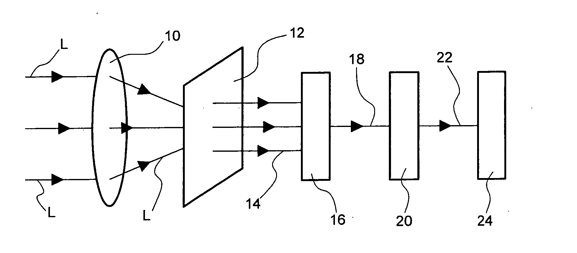
  • Optical lens assembly for a handheld electronic device
  • Optical lens assembly for a handheld electronic device
  • Optical lens assembly for a handheld electronic device

Examples


Embodiment Construction

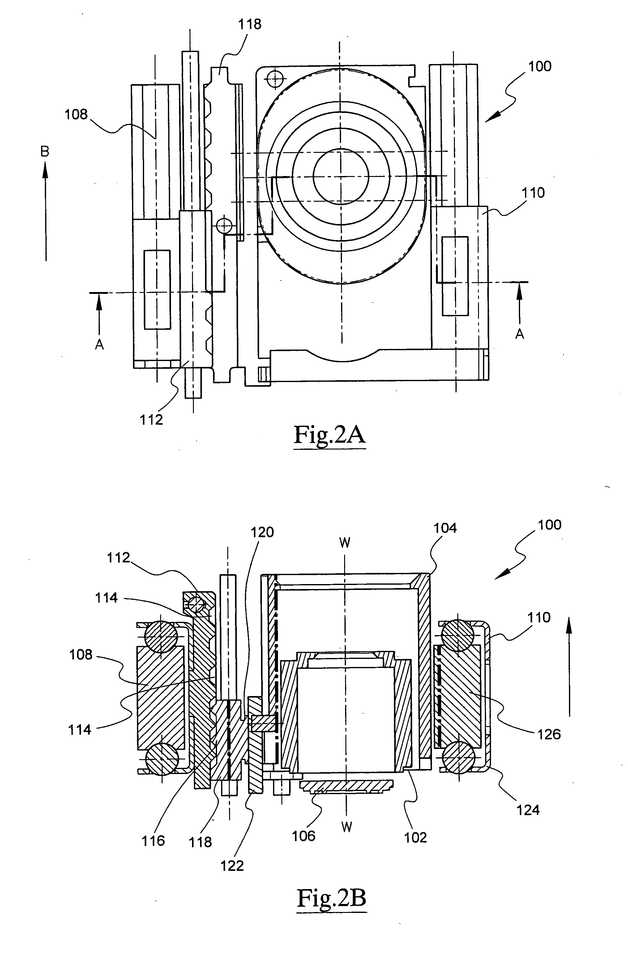
[0048] An optical lens assembly according to a first preferred embodiment of this invention is shown in FIGS. 2A and 2B, and generally designated as 100. The assembly 100 includes an inner lens tube 102 telescopically received within and movable relative to an outer lens tube 104 in a lengthwise direction. Each of the inner tube 102 and outer tube 104 carries a piece of lens or a group of lenses (not shown), in which all their optical axes are aligned about a common longitudinal optical axis W-W. At a lower end of the lens assembly 100 is mounted a light-sensitive component 106, such as a CCD or a CMOS.

[0049] The lens assembly 100 has two piezo electric ultrasonic linear motors 108, 110. An appropriate piezo electric ultrasonic linear motor (hereinafter called “USM”) which may be used for realizing the various embodiments of the present invention is a self-vibration type linear ultrasonic motor described in International Patent Application No. PCT / EP2005 / 004236 filed by Physik Inst...


PUM


Abstract

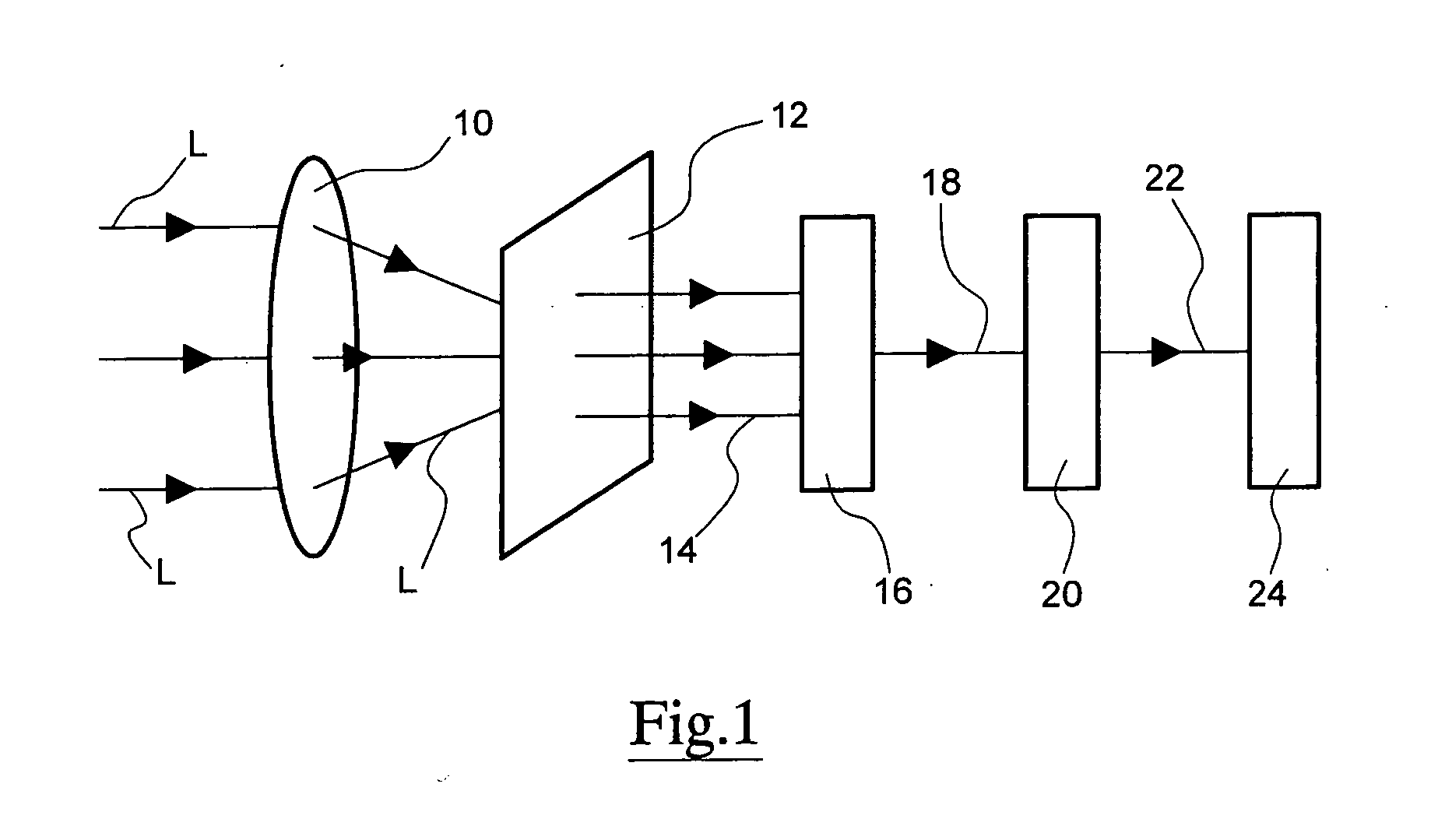
An optical lens assembly is disclosed as including a light-sensitive member; first and second lenses / lens groups with their respective optical axis aligned with each other along a common optical axis; and first and second piezo electric ultrasonic linear motors; in which the first motor is operable to move the first and second lenses / lens groups relative to each other to vary their distance; and the second motor is operable to move the light-sensitive member or at least one of the first and second lenses / lens groups to vary the distance between the light-sensitive member and the lens / lens group. A handheld electronic device, e.g. a mobile phone or a personal digital assistant, with digital camera function, and including such an optical lens assembly is also disclosed. There is further disclosed an optical lens system including an optical system, a light-sensitive component, an auto-focus judge for determining if an image captured by the light-sensitive component is in focus, and a driving IC for driving a piezo electric ultrasonic linear motor in response to the result arrived at by the auto-focus judge.

Description

[0001] This invention relates to improvements on an optical lens assembly for use in a handheld electronic device, e.g. mobile phone or personal digital assistant (PDA), and in particular such an assembly installed in such a handheld electronic device, allowing photographs to be taken digitally. BACKGROUND OF THE INVENTION [0002] There are now many mobile phones with camera functions. Much research and development has been done on the lens assemblies in such mobile phones. However, as most such mobile phones make use of common optical lens assemblies, it is very difficult to improve the performance of the lens assemblies, in particular to allow for movement of the lenses in such a small space. Some cameras in such mobile phones use fixed-focus lenses, and some use variable-focus lenses. Either way, it is difficult to come up with small-sized optical lens assemblies for use in such handheld devices, e.g. mobile phones. [0003] Built-in and add-on taking lenses for mobile phones are of...

Claims


Application Information

Patent Timeline
Patent Type & Authority Applications(United States)
IPC IPC(8): G02B13/16H04N5/225G02B7/02G02B7/10G02B13/00H10N30/80
CPCG02B7/021G02B7/102G02B13/0065G02B13/009
Inventor TIROLE, NICOLASGUIBELIN, JOELYAN, SONGTAOHU, WEIHUANG, GUOHUA
Owner MAXFORD TECH LTD
Learn More