Deployable monitoring device having self-righting housing and associated method

a monitoring device and self-righting technology, applied in the field of surveillance equipment, can solve the problems of limited scene access, limited effectiveness of visual devices in such situations, limited use of visual devices, etc., and achieve the effect of facilitating self-righting

Inactive Publication Date: 2006-06-22
CHANG IND INC
View PDF36 Cites 11 Cited by
  • Summary
  • Abstract
  • Description
  • Claims
  • Application Information

AI Technical Summary

Benefits of technology

This patent describes a monitor that can be placed on top of something and easily moved around without falling over. It has a part called a stabilizer that stops it from spinning too much while moving. When the monitor gets back up after being pushed down or rolled across something, it naturally wants to stand upright again.

Problems solved by technology

This patent describes a technical problem that needs to be solved: how to monitor a specific area or scene from a safe distance without compromising its privacy or security? Current solutions like binoculars or cameras require a clear line of sight and can't easily adapt to changing circumstances. A new monitoring device is needed that overcomes these limitations and provides an easy way to safely observe what happens in real-time.

Method used


Image

  • Deployable monitoring device having self-righting housing and associated method
  • Deployable monitoring device having self-righting housing and associated method
  • Deployable monitoring device having self-righting housing and associated method

Examples


Embodiment Construction

[0020] The present invention now will be described more fully hereinafter with reference to the accompanying drawings, in which preferred embodiments of the invention are shown. This invention may, however, be embodied in many different forms and should not be construed as limited to the embodiments set forth herein; rather, these embodiments are provided so that this disclosure will be thorough and complete, and will fully convey the scope of the invention to those skilled in the art. Like numbers refer to like elements throughout.

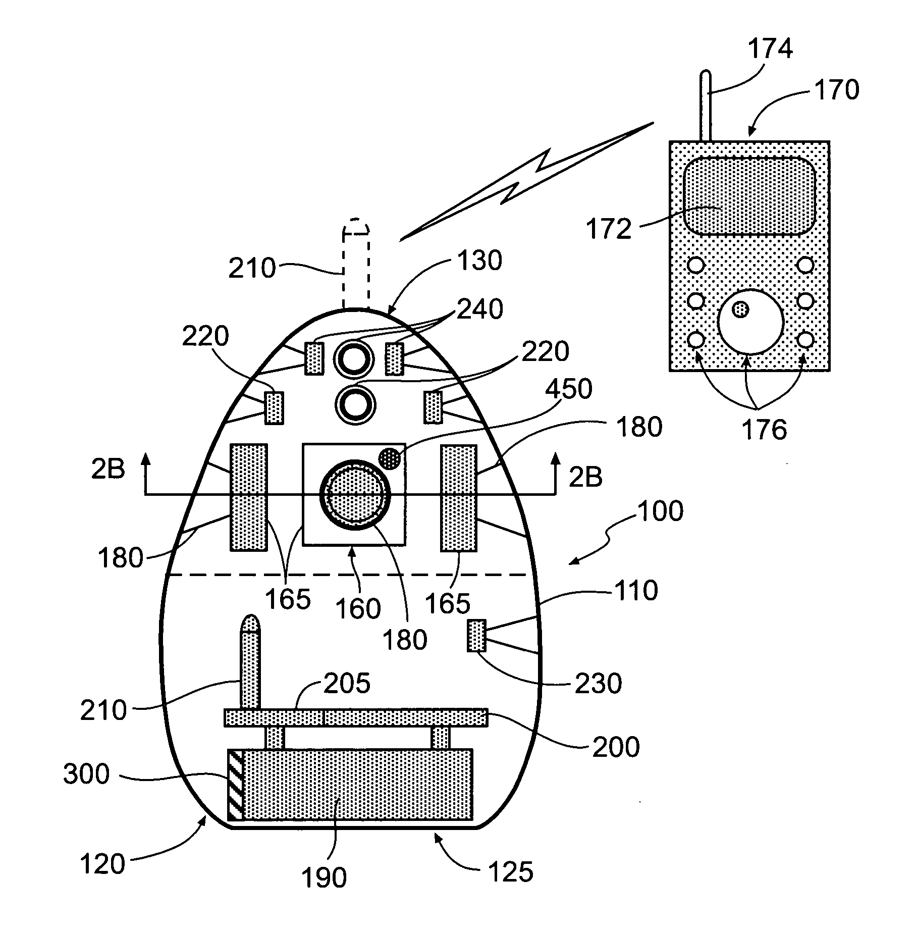
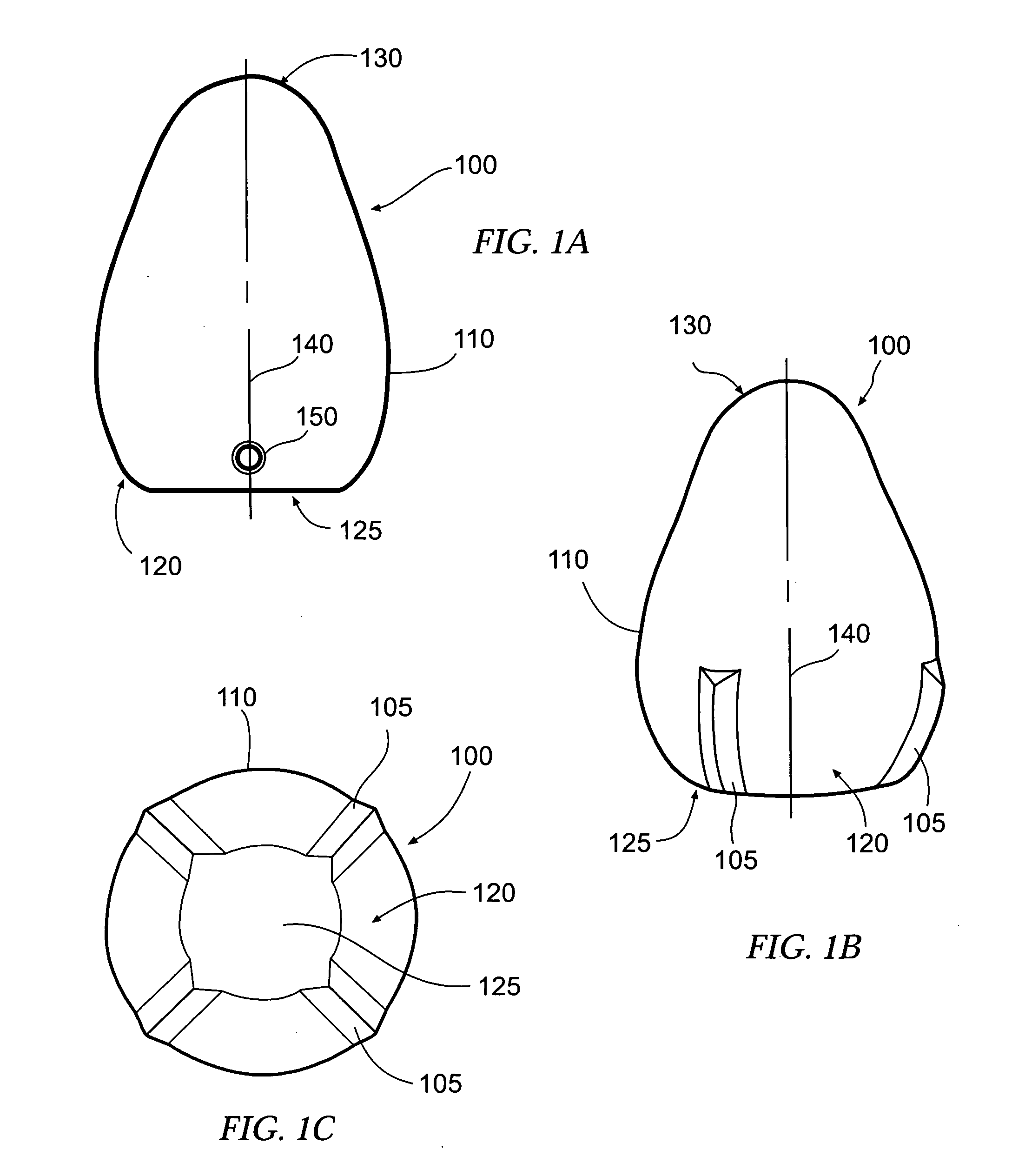
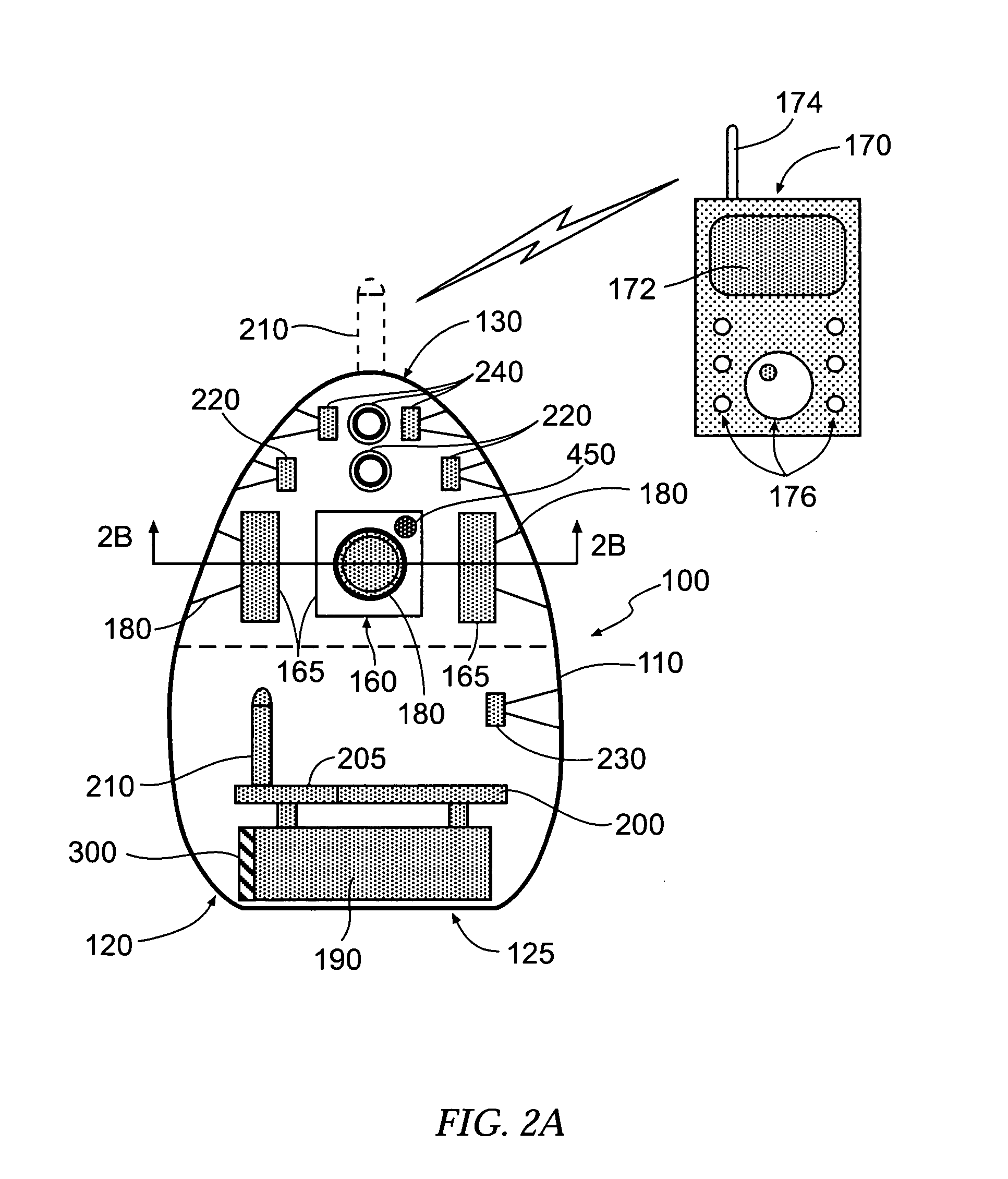
[0021]FIG. 1A schematically illustrates one embodiment of a deployable monitoring device according to the present invention, the device being generally indicated by the numeral 100. According to one advantageous embodiment of the present invention, the device 100 is configured so as to be self-righting upon deployment. Accordingly, the device 100 includes a housing 110 which, in one instance, is ovately shaped with a relatively wide base 120 and an oppos...


PUM


Abstract

A deployable monitoring device is provided comprising a self-righting housing and a video capturing device. The housing has a base and an opposed end disposed along an axis, with a center of gravity disposed about the base, and is self-righting along the axis. The housing, when righted, is supported by the base. The video capturing device captures video data of an external scene. At least one stabilizer device is operably engaged with the housing about the base. Each stabilizer device extends radially outward of the base and substantially axially along an outer surface thereof, and is configured to stop rotation of the housing about the axis before the housing is righted, following deployment of the housing. The video data can be transmitted by a transceiver module to a station remotely disposed from the housing, to provide a remote visual depiction of the scene. An associated method is also provided.

Description


Claims


Application Information

Patent Timeline
Owner CHANG IND INC
Why Eureka
Try Eureka