Device and method for antenna matching

a technology of antenna matching and device, applied in the direction of electrical equipment, transmission, etc., can solve the problems of decreasing the working efficiency of the transceiver and increasing the current consumption, and achieve the effect of maximizing the intensity of both the transmission signal and the receiving signal

Inactive Publication Date: 2005-02-24
BENQ CORP
View PDF18 Cites 462 Cited by
  • Summary
  • Abstract
  • Description
  • Claims
  • Application Information

AI Technical Summary

Benefits of technology

[0011] Applying the aforementioned antenna matching device and method of the same will enable the transceiver to have an optimal matching state at the antenna side, such that the intensity of both the transmission signal and the receiving signal is maximized.

Problems solved by technology

Nevertheless, by doing so, the current consumption will increase, and the working efficiency of the transceiver will decrease.

Method used


Image

  • Device and method for antenna matching
  • Device and method for antenna matching
  • Device and method for antenna matching

Examples


Embodiment Construction

[0020] For your esteemed members of reviewing committee to further understand and recognize the fulfilled functions and structural characteristics of the invention, several preferable embodiments cooperating with detailed description are presented as the follows.

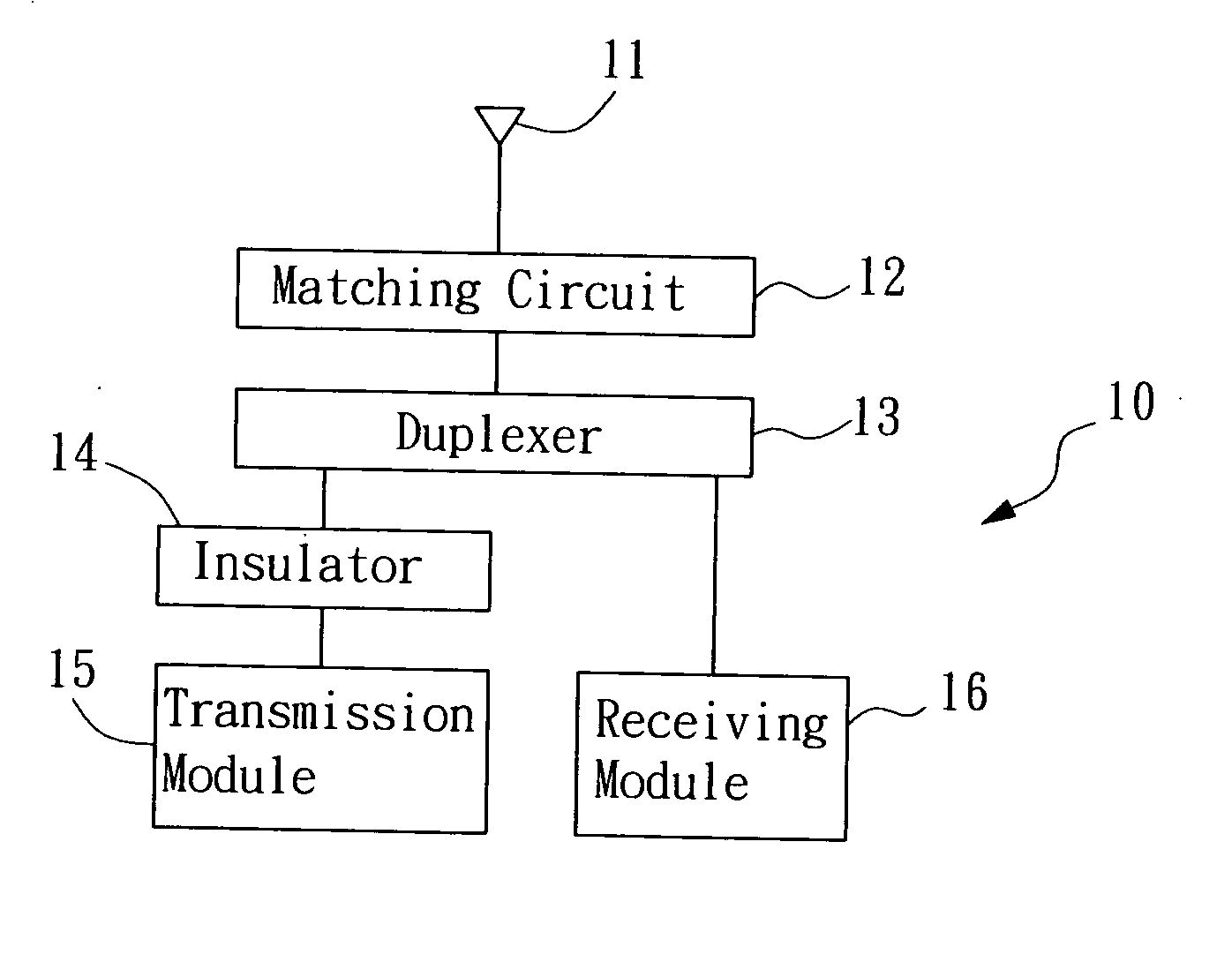
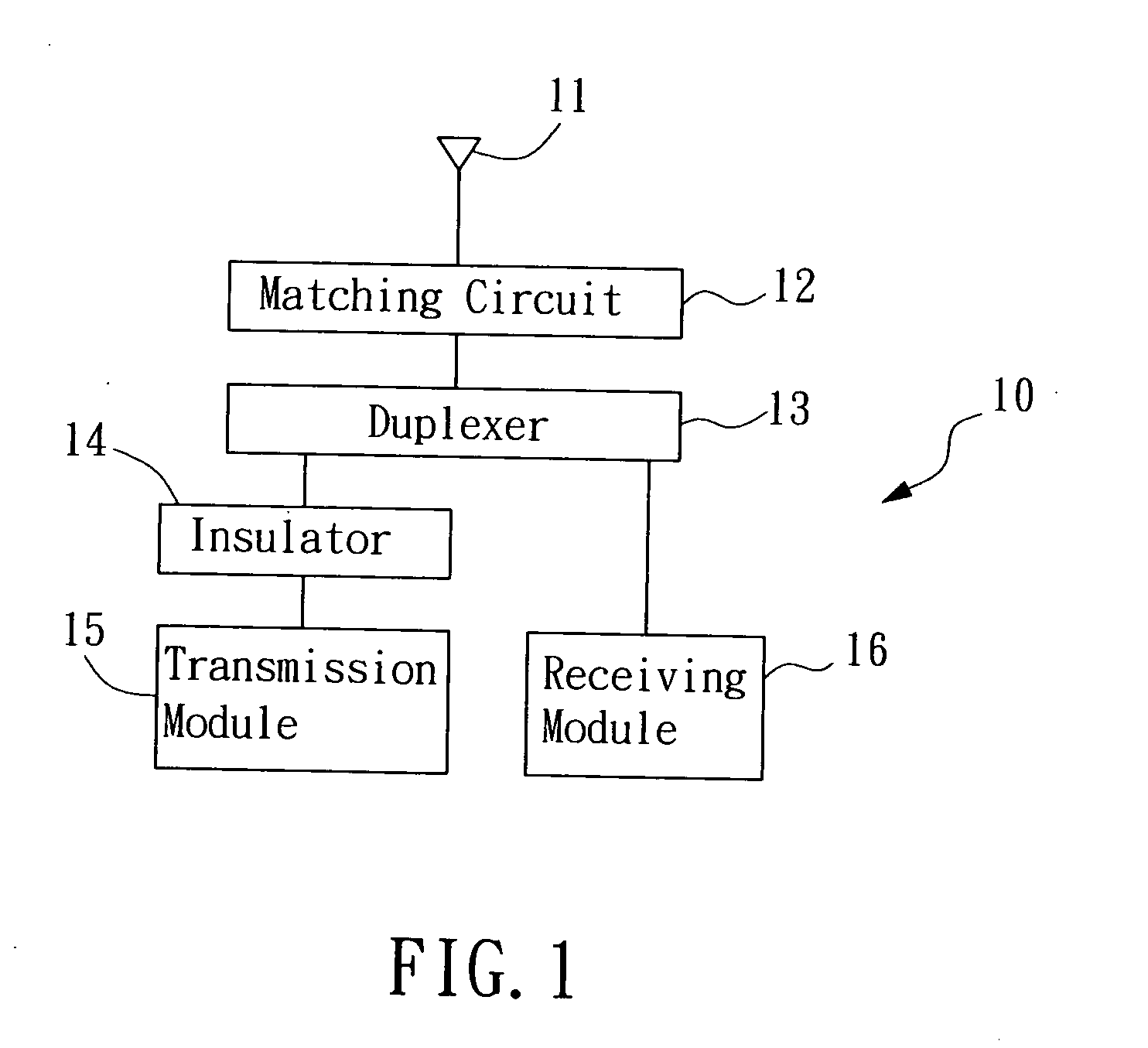
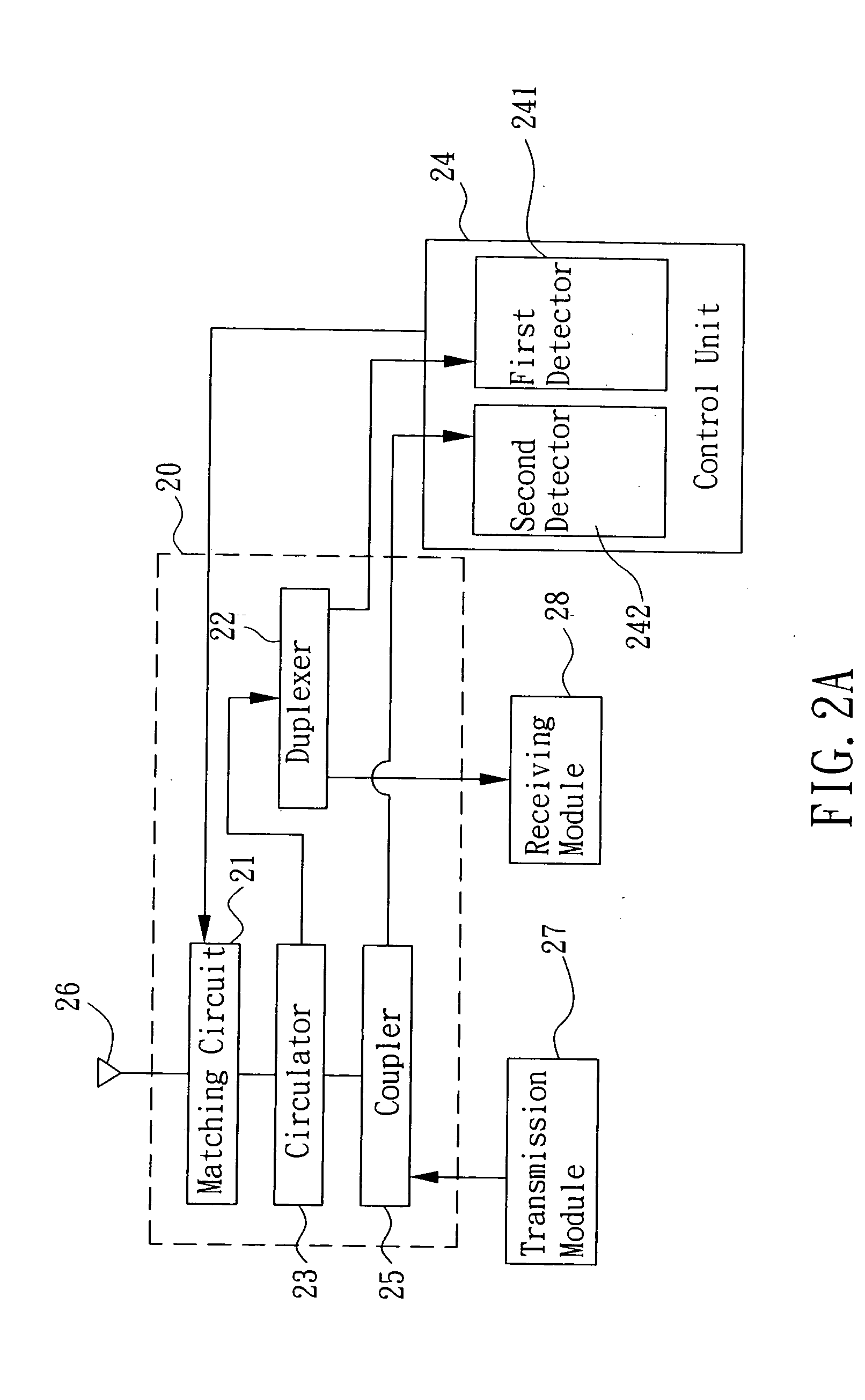
[0021] Please refer to FIG. 2A, which is a first preferred embodiment of the antenna matching device adapted for a transceiver according to the present invention. The transceiver has a transmission module 27 and a receiving module 28. The antenna-matching device 20 includes: a matching circuit 21, a duplexer 22, a circulator 23, a control unit 24, and a coupler 25.

[0022] The matching circuit 21 having a first end and a second end, the second end is coupled to an antenna 26, is capable of adjusting the matching impedance of the antenna 26 according to an adjusting signal such that a reflection signal of the antenna 26 is minimized to reach the optimization of matching, and the matching circuit 21 will also generate a reflec...


PUM


Abstract

The present invention provides a device and method for antenna matching applied in a transceiver. Wherein, the transceiver has a transmission module and a receiving module. The antenna matching device includes a matching circuit, a duplexer, a circulator, a control unit, and a coupler. Wherein, the matching circuit adjusts the matching impedance according to an adjusting signal and generates a reflection signal. The duplexer receives the reflection signal and a receiving signal and respectively sent the received two signals to the control unit and the receiving module according to their frequencies. The control unit, according to the reflection signal, estimates the adjusting signal for adjusting the matching circuit to an optimal state of the load impedance of the matching antenna, such that the antenna gain may is maximized, and a best efficiency is obtained no matter during receiving or transmission.

Description

FIELD OF THE INVENTION [0001] The present invention relates to a device and method for antenna matching, more particularly, to an antenna matching device and method for antenna matching capable of reaching a matching optimization by means of a circulator and a duplexer. BACKGROUND OF THE INVENTION [0002] In a traditional transmission system, such as the modulation system of CDMA (Code Division Multiple Access) or the modulation system of FDMA (Frequency Division Multiple Access) with reference to FIG. 1, a transceiver 10 includes: an antenna 11, a matching circuit 12, a duplexer 13, an insulator 14, a receiving module 16, and a transmission module 15. Wherein, the duplexer 13 has function of frequency division transmitting and signal receiving, and the insulator 14 is unidirectional. Thus, while the power transmitted by the transmission module 15 is being transmitted to the antenna 11 through the insulator 14, the duplexer 13, and the matching circuit 12, since the insulator 14 is u...

Claims


Application Information

Patent Timeline
Patent Type & Authority Applications(United States)
IPC IPC(8): H04B1/04
CPCH04B1/0458
Inventor HO, CHIA-CHENG
Owner BENQ CORP
Why Eureka
Try Eureka