Optical sensor for contactless pressure measurements

a sensor and optical sensor technology, applied in the field of optical sensors, can solve the problems of less reliable, more sensitive mechanical vibration of “interferometric” sensors, and even more expensive of “interferometric” sensors, and achieve the effect of increasing reliability

Active Publication Date: 2015-10-08
LASERPOINT
View PDF6 Cites 5 Cited by
  • Summary
  • Abstract
  • Description
  • Claims
  • Application Information

AI Technical Summary

Benefits of technology

[0016]In view of the state of the art, it is an object of the present to provide an optical sensor for contactless pressure measurements which

Problems solved by technology

“Interferometric” sensors have the advantage to measure pressure with an higher resolution than the “Intensity modulated” ones but on the other side, “Interferometric” sensors are more sensitive to mechanical vibrations (often present in industrial environment) and less reliable due to the use of more complicated optical design related to the interferometers.
The use of interferometer and the need of a coherent LASER source makes the “Interferometric” sensors even more expensive than the rocky and robust optical “Intensity modulated” sensor where low cost not-coherent LED source may be used.
Even if both kinds of these sensors are widely used in industrial environment where harsh conditions are reached, many of the previous listed advantages are not applicable anymore for this kind of sensors; specifically, this sensor needs a mechanical contact between the transducer chip and the pressure sensing diaphragm.
Even if the transducer chip is typically shielded in a metal enclosure avoiding EMI problems, the electronics needed for detection and sig

Method used


Image

  • Optical sensor for contactless pressure measurements
  • Optical sensor for contactless pressure measurements
  • Optical sensor for contactless pressure measurements

Examples


Embodiment Construction

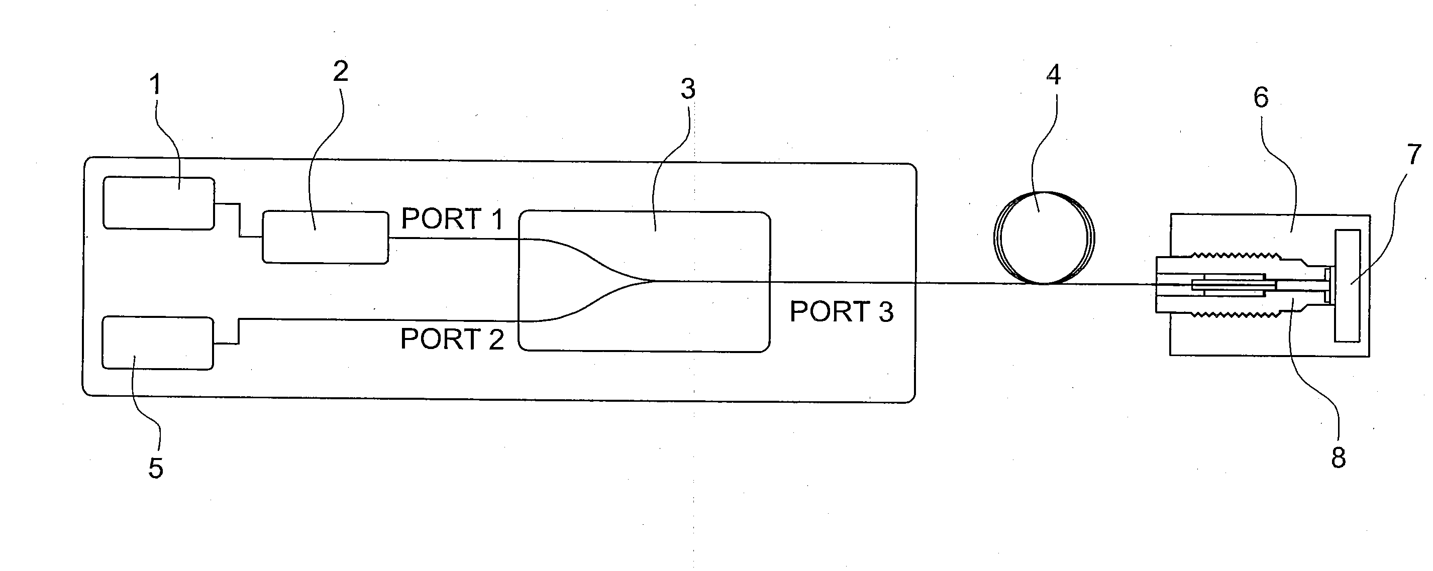
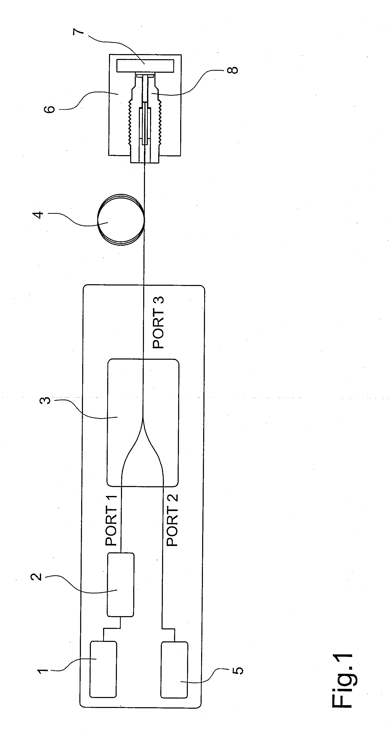
[0037]An optical sensor for pressure measurements according to the present invention is shown in FIGS. 1-3. Specifically the optical sensor comprises (FIG. 1), an optical source 1, for example a LED or a LASER source, which is connected by means of a fiber to an optical isolator 2 and the optical isolator is further optically connected to an input port PORT 1 of a directional optical coupler 3. The optical isolator 2 is needed to avoid that the light back reflected reaches the optical source possibly producing some optical instability of the source itself. The directional optical coupler 3 comprises another input port PORT 2 which is optically connected by means of a fiber with a receiver 5, for example a PIN or an APD; the output port PORT 3 of the directional optical coupler 3 is optically connected to the input of a waveguide means 4, for example a single mode or multimode optical fiber. The length of this waveguide means 4 may be done long enough from few meters to some kilomete...


PUM


Abstract

An optical sensor for pressure measurements is described which comprises a sensor head (8) including: -a diaphragm (9) having a first surface (91) in contact with a fluid of which the pressure has to be measured and a second surface (92) opposite to the first surface, -a body with a tubular cavity (200), -means (92, 10) arranged inside the tubular cavity, associated with the second surface of the diaphragm and movable longitudinally inside said tubular cavity in response to the deformation of the diaphragm, said means including a reflective surface (92, 102), -an end part (12) of waveguide means (4) arranged inside the tubular cavity and having the end surface (11) faced to and not in contact with the reflective surface (92, 102) of said means, said waveguide means being connected to a light source (1) and a receiver (5) respectively to send to said means the light beam (50) deriving from the light source and to collect at the receiver the light beam (60) reflected from the reflective surface of said means, the intensity of the collect light beam being dependent on the distance (D) between the end surface of the end part of waveguide means and the reflective surface. The end surface (11) of the end part (12) of waveguide means is tilted with respect to a plane orthogonal (B) to the optic axis (A) of a first angle (α) having a value such that the incident angle (θa) of the light beam deriving from the light source is less than the critical angle (θc-air) between the waveguide means and the air and greater than the critical angle (θc) of the waveguide means, and the reflective surface (102, 92) of said means is tilted with respect said plane (B) orthogonal to the optic axis (A) of a second angle (β) equal to the escaping angle of the light beam from said end surface (11) of the end part (12) of waveguide means.

Description

BACKGROUND OF THE INVENTION[0001]Optical sensors for pressure measurement may be generally divided into two main different families according to the different approach used to measure the pressure parameter: “Interferometric” and “Intensity modulated” optical sensors. In the “Interferometric” optical sensors, the pressure is measured by the phase change between the incoming optical probe beam and the out-coming from an optical pressure sensing element (using Bragg, Fabry-Perot, Michelson, Mach-Zehnder interferometers). In the “Intensity modulated” optical sensors, the pressure is directly measured by the intensity change between the incoming optical probe beam and the out-coming one from an optical pressure sensing element (typically a reflective surface of a pressure sensing diaphragm) In the “Intensity modulated” optical sensors, fiber optic is used to drive incoming optical beam in front of the pressure sensing reflective diaphragm and to collect the light beam reflected by the d...

Claims


Application Information

Patent Timeline
IPC IPC(8): G01L7/08
CPCG01L7/086G01L11/02
Inventor BRINCIOTTI, ANDREACIBINETTO, LUCIO
Owner LASERPOINT
Why Eureka
Try Eureka