Continuous-wave ultraviolet laser

a laser and continuous wave technology, applied in the field of shortwavelength diodepumped solid state lasers, to achieve the effects of improving performance, increasing laser stability, and efficient frequency conversion

Active Publication Date: 2010-09-21
COBOLT
View PDF14 Cites 6 Cited by
  • Summary
  • Abstract
  • Description
  • Claims
  • Application Information

AI Technical Summary

Benefits of technology

[0012]The present invention provides a concept for a solid-state laser facilitating generation of continuous-wave light at wavelengths below 400 nm It should be understood, however, that the inventive concept may be employed also for generation of longer wavelengths.
[0015]According to this invention, mixing of the fundamental wave and the frequency-doubled wave to generate the frequency-tripled wave of radiation is effected by a quasi-phasematching structure of second or higher order. This is a particularly useful feature of the present invention, since it allows for the use of a grating structure having a larger period compared to a grating designed for first order quasi-phasematching. By avoiding the use of very fine-pitch gratings in this manner, i.e. by using higher-order quasi-phasematching, the non-linear element for generating the frequency-tripled wave can be manufactured in a simple, reliable and cost-efficient way.
[0021]Suitably, the first and second non-linear elements may be implemented as separate regions in a common body. In this manner, the number of optical interfaces in the cavity is reduced and optical losses are minimized. This may provide for higher output powers for the frequency-tripled wave, and save costs in production. In such case, the non-linear material needs to be transparent for all the interacting waves. For example, PPSLT may then be used.
[0025]It is also preferred to have the resonant cavity divided into at least three separate branches. To this end, the cavity may be defined by a first and a second end mirror and a first and a second folding mirror. A first branch is located between the first end mirror and the first folding mirror, a second branch is located between the first and the second folding mirrors, and a third branch is located between the second folding mirror and the second end mirror. The active body for generating the fundamental wave may suitably be located in the first branch, and the first and second non-linear elements may suitably be located in the second branch. All mirrors are designed for high reflection at the fundamental wave, in order to maximize the intensity of the fundamental wave circulating within the cavity. By maximizing the intensity of the fundamental wave and by arranging the non-linear elements within the cavity, the conversion efficiency for the generation of the frequency-doubled wave and the frequency-tripled wave is enhanced.
[0027]In order to increase the stability of the laser, and in order to provide for efficient frequency conversion, the cavity preferably includes a wavelength filter, such as a Lyot filter. Lyot filters are per se known in the art, and need not be explained in detail here. Most preferably, such Lyot filter is located in the third branch of the cavity. By locating the Lyot filter in a separate branch of the cavity, performance is improved and, in particular, temperature control of the Lyot filter components is simplified. In this context, it should be noted that the birefringent crystal for the Lyot filter is separate from any of the frequency-converting crystals.

Problems solved by technology

When designing a continuous-wave frequency converted laser, it is a challenge to obtain sufficient output power at the frequency-converted wavelength.

Method used


Image

  • Continuous-wave ultraviolet laser
  • Continuous-wave ultraviolet laser
  • Continuous-wave ultraviolet laser

Examples


Embodiment Construction

[0035]Before going into a detailed description of the preferred embodiments shown on the drawings, one laser according to the present invention will be explained in general terms.

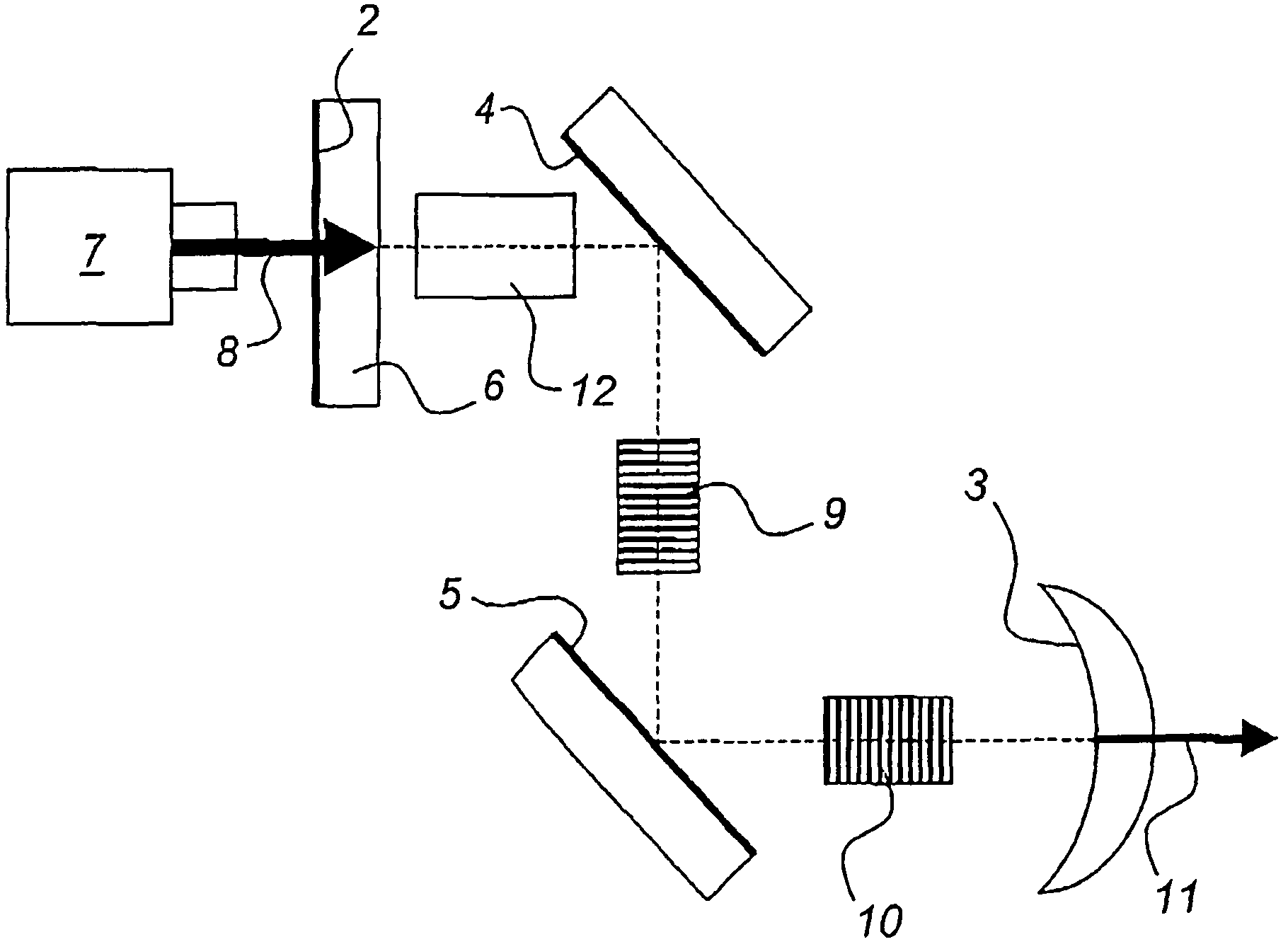
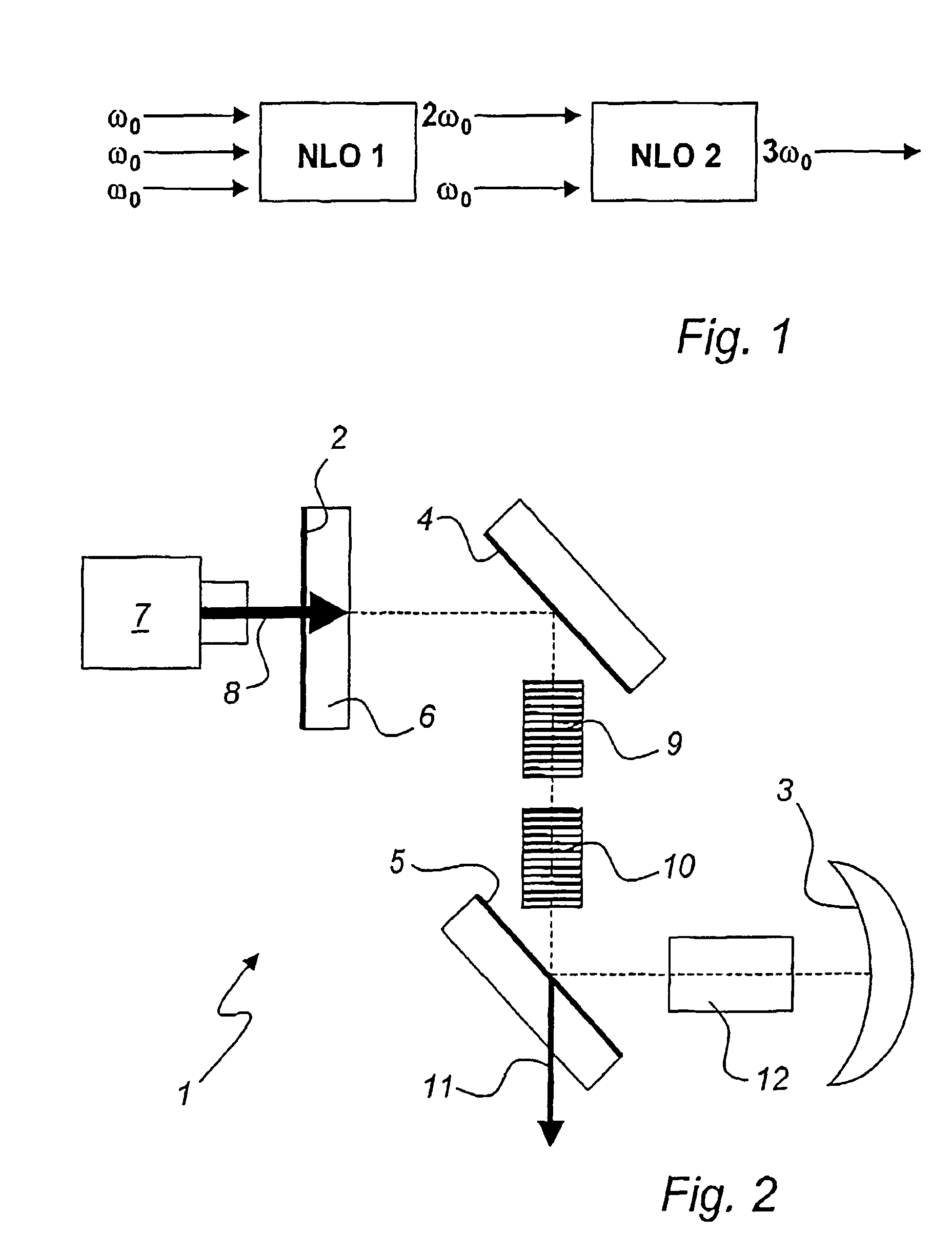
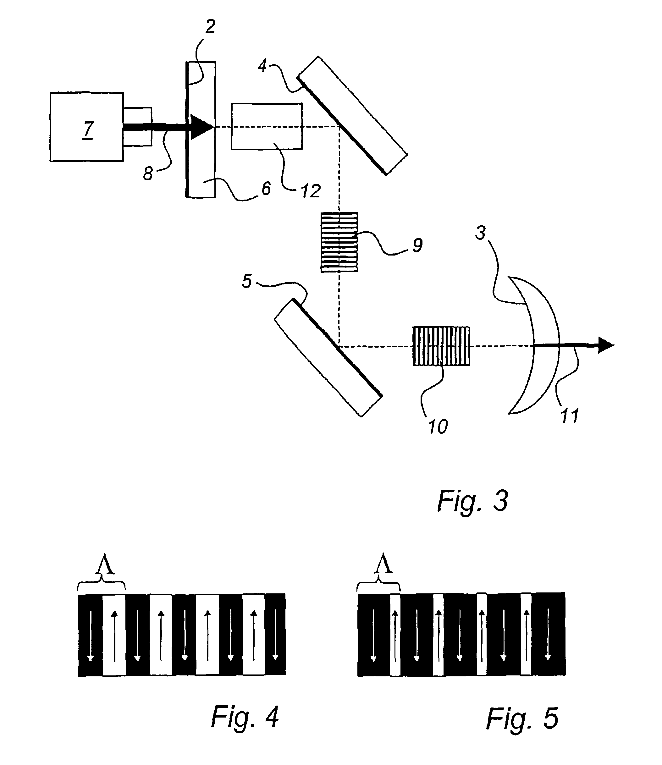
[0036]A laser according to the present invention may be designed for emission at 355 nm (i.e. ultraviolet laser light). A diode laser for pumping at 808 nm is used to provide energy to the active body (gain medium of the laser), which is comprised of Nd:YVO4. Laser emission at 1064 nm is obtained by using a resonant optical cavity in a folded configuration enclosing the Nd:YVO4 crystal. Two non-linear optical elements are placed inside the resonant cavity. The first non-linear element is designed for optimum frequency conversion of the 1064 nm radiation to 532 nm (i.e. frequency doubling), and the second non-linear element is designed for optimum frequency conversion (sum frequency mixing) of the 1064 nm radiation and the 532 nm radiation to 355 nm. Good beam quality is ensured by using a curved end mirror ...


PUM


Abstract

A laser is disclosed, which is suitable for efficient generation of continuous-wave laser light having a wavelength of about 400 nm or less. The short-wavelength light is generated by first frequency-doubling a fundamental wave, and then sum-frequency mixing the frequency-doubled wave and the fundamental wave. The non-linear interactions are effected by means of quasi-phasematching structures inside a resonant cavity where the fundamental wave is circulating. The sum-frequency mixing is effected using second or higher order quasi-phasematching, which allows for wider domains to be inverted for the quasi-phasematching structure compared to first order quasi-phasematching. Preferably, the sum-frequency mixing is effected using periodically poled stoichiometric lithium tantalate (PPSLT) for second or third order quasi-phasematching.

Description

TECHNICAL FIELD[0001]The present invention generally relates to short-wavelength diode-pumped solid state lasers. More particularly, the present invention relates to continuous-wave diode-pumped solid state lasers capable of emitting wavelengths below about 400 nm.TECHNICAL BACKGROUND[0002]In many biomedical applications, laser light is used to induce fluorescence from biomolecules or biological substances that are studied. For example, such substances may include genes, proteins, cells and tissue. In some cases, scattering or absorption of the light is also employed in the measurements. The fluorescence is typically generated by means of a fluorophore or “biomarker” that has been chemically attached to the substances to be studied. Such fluorophores may, for example, be fluorescent proteins or dyes. The fluorophores often require excitation at a specific wavelength of light.[0003]There is currently a trend on the biomedical instrumentation market to go from large and expensive anal...

Claims


Application Information

Patent Timeline
Patent Type & Authority Patents(United States)
IPC IPC(8): H01S3/109H01S3/0941
CPCG02F1/3532G02F2001/354G02F1/354
Inventor KARLSSON, HAKANHELLSTROM, JONAS
Owner COBOLT
Why Eureka
Try Eureka