Hard X-Ray Photoelectron Spectroscopy Apparatus

a technology of photoelectron spectroscopy and hard x-ray, which is applied in the field of hard x-ray photoelectron spectroscopy apparatus, can solve the problems of reducing the efficiency of conventional photoelectron spectroscopy, so as to increase the efficiency of photoelectron collection and maximize the efficiency of photoelectron

Inactive Publication Date: 2016-11-10
KOBAYASHI KEISUKE +1
View PDF2 Cites 6 Cited by
  • Summary
  • Abstract
  • Description
  • Claims
  • Application Information

AI Technical Summary

Benefits of technology

[0040]There has been two big problems in the above-described prior art, which is: size of the X-ray source (i.e., size of X-ray monochromater crystals) and size of the mechanism of a target part) is restricted due to size of the analysis chamber (6) and higher output is limited, accordingly; the vacuum of the X-ray source and the vacuum of the analysis chamber cannot be separated. In an experimental method, called NAP (Near Ambient Pressure photoelectron spectroscopy) or HiPP (High Pressure Photoelectron spectroscopy), gas is introduced into the analytical chamber and thus X-ray source (3) in FIG. 5 would also be exposed to gas, which could cause a problem that an electron gun contained in the X-ray source would be unable to bear gas introduction because it needs high vacuum.
[0041]However, the hard X-ray photoelectron spectroscopy apparatus according to the first aspect of the present invention comprises a configuration having the X-ray source and the analysis chamber separated, and thus can solve all of these problems. In the hard X-ray photoelectron spectroscopy, photoionization cross sections are smaller than those obtained in the conventional photoelectron spectroscopy, and thus it is also indispensable to practically increase the photoelectron collection efficiency as much as possible. Using the hard X-ray photoelectron spectroscopy apparatus, according to the first aspect of the present invention, it is possible not only to separate the vacuum of the X-ray source and that of the analysis chamber, but also to maximize the photoelectron collection efficiency.
[0042]The hard X-ray photoelectron spectroscopy apparatus according to the second aspect of the present invention is configured such that the above-described analysis chamber (14) and the above-described X-ray source (3) are integrated, the analysis chamber part (14a) and the X-ray source (3) are arranged in the same structure, and a vacuum area of the analysis chamber part (14a) and the X-ray source (3) is divided by the partition (12), so that it has remarkable effects that enable downsizing of the whole apparatus, separation of the vacuum areas of X-ray source (3) and the analysis chamber part (14a) (photoelectron analysis part), and maximization of the photoelectron intensity. Furthermore, it is possible to realize a configuration which can be used by changing two X-rays having different energy by applying another invention “X-ray generator and analyzer” (U.S. Pat. No. 5,550,082, inventors: KOBAYASHI, Keisuke; YAMAZUI, Hiromichi, IWAI, Hideo, OBATA, Masaaki).
[0043]According to the hard X-ray photoelectron spectroscopy apparatus according to the third aspect of the present invention, in a structure where the monochromater crystal assembly (9), the electron gun (3b) and the target (7) are separated from the vacuum area of the analysis chamber (14) and placed outside, it is possible to excite a high-speed rotating water-cooled target (7) with a high-output focusing electron gun (3b) and to realize a monochromatized CrK α-ray source with the flux intensity and flux density which are 10 times or more of an output obtained by using the stationary target (7).

Problems solved by technology

Thus, photoelectron spectroscopy is a very useful analytical method and has been widely used, but has a big problem.
Then, the original information such as its own energy and momentum will be lost, thereby turning the photoelectron into insignificant background in a photoelectron spectrum.
That is, the conventional photoelectron spectroscopy is very surface-sensitive and would measure only dirt on a sample of which surface has not been sufficiently cleaned out.

Method used


Image

  • Hard X-Ray Photoelectron Spectroscopy Apparatus
  • Hard X-Ray Photoelectron Spectroscopy Apparatus
  • Hard X-Ray Photoelectron Spectroscopy Apparatus

Examples


embodiment 1

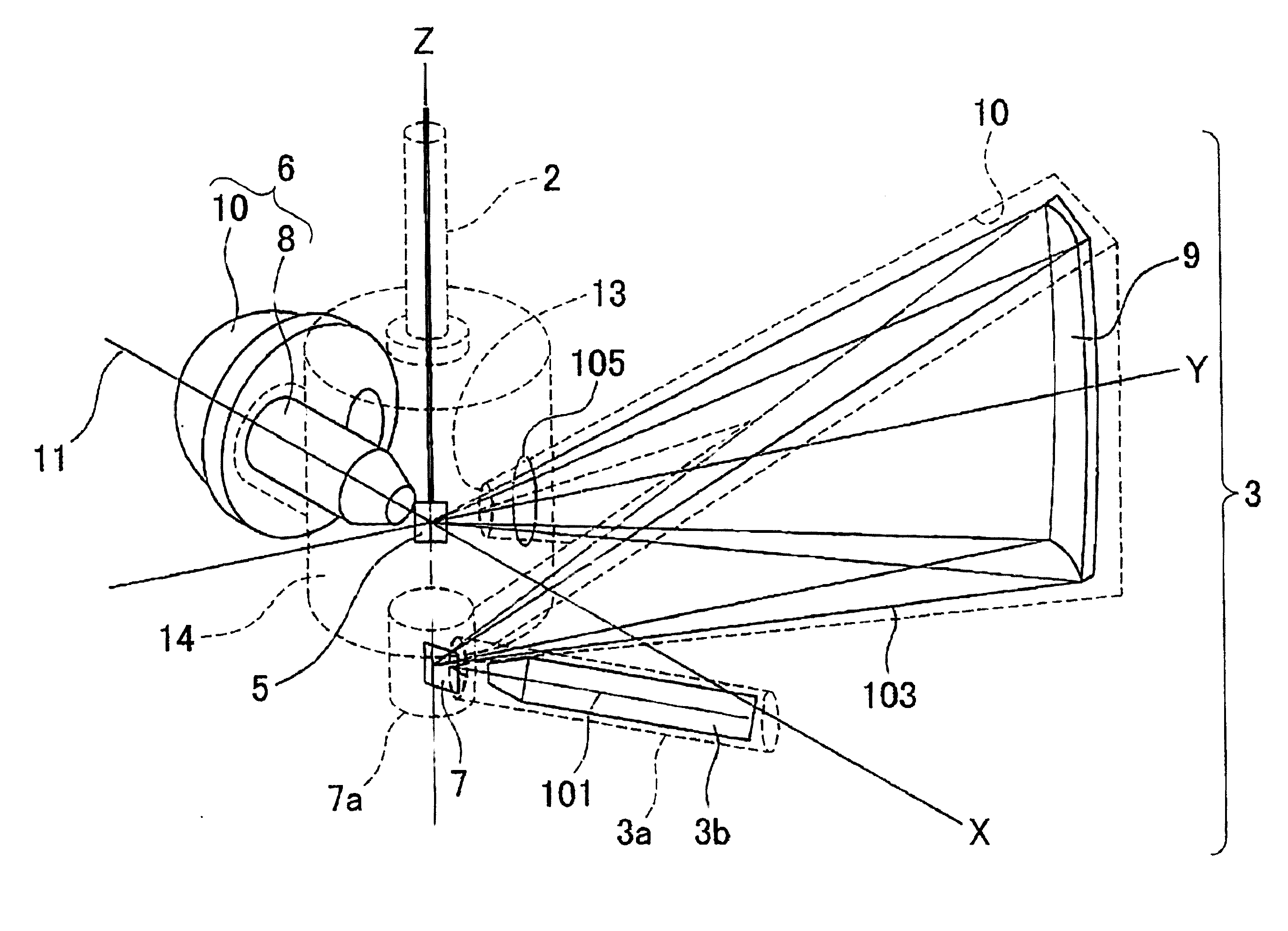
[0057]FIG. 6 is an illustration showing a configuration of the photoelectron spectroscopy apparatus according to the embodiment 1 of the present invention, and FIG. 7 is an illustration explaining a principle of a monochromatized X-ray source and a geometrical relationship between the X-ray source and a sample according to the present invention. Referring to FIG. 6 and FIG. 7, an electron beam (101) is accelerated and irradiated to a target (7) to generate an X-ray. For example, in the case of a target of Cr (hereinafter simply referred to as “Cr target”), the irradiation is typically conducted by focusing an electron beam accelerated to 20-30 keVit to about 100 microns. Then, X-ray beam (X-ray beam prior to monochromatization including a Bremsstrahlung X-ray etc.) (103) is emitted from the Cr target wherein a CrKα-ray having a peak at energy of 5.4 keV is overlapped with the Bremsstrahlung X-rays (a continuous spectrum emitted in the process where an electron slows down when it col...

embodiment 2

[0072]Another embodiment will be explained below which satisfies the conditions for the above-mentioned spatial configurations.

[0073]The inventors adopts in this embodiment the knowledge relating to another invention “X-Ray Generator and Analyzer” (U.S. Pat. No. 5,550,082; Inventors: KOBAYASHI, Keisuke, YAMAZUI, Hiromichi, IWAI, Hideo, and KOBATA, Masaaki), in which a configuration of the double-ray source switching and utilizing an AlKα-ray and CrKα-ray is suggested.

[0074]FIG. 9 shows an apparatus of this embodiment. This embodiment has a structure in which the analysis chamber and the X-ray source are integrated and the vacuum of the analysis chamber part and that of the X-ray source are divided by a partition to lead the X-ray through an X-ray window provided at the partition to the analysis chamber.

[0075]The target (7) is irradiated with an electron beam by the electron gun (3b) to generate an X-ray. There is an area coated with Al and Cr on the substrate of the target (7). The ...

embodiment 3

[0078]Yet another embodiment will be explained below which satisfies the conditions for the above-mentioned spatial configuration. In the embodiment 1, in order to achieve large X-ray flux, a structure is adopted which achieves a large acceptance angle of the monochromater crystal assembly, but there is a spatial restriction for this structure. It is considered that the output of the electron gun (3b) exciting the target for further increase of the X-ray flux is increased. However, if the output of the electron beam is increased exceeding the cooling capacity of the target (7), the target layer (7) will be damaged, since the most of energy of the electron beam turn into heat within the target layer (7). If the size of the spot (footprint (FP)) on the target (7) of the electron beam is increased, the density of the generated heat decreases, thereby preventing the damage to the target (7). However, the spot size on the target (7) of the electron beam corresponds to the size of the X-r...


PUM

PropertyMeasurementUnit
angleaaaaaaaaaa
energyaaaaaaaaaa
sizeaaaaaaaaaa

Abstract

[Problem]
The present invention aims to solve the problems that size of X-ray monochromater crystal assembly is restricted and the vacuum of the X-ray source and the vacuum of the analysis chamber cannot be separated.
[Solution]
A hard X-ray photoelectron spectroscopy apparatus comprises an X-ray source, an analyzer, a sample manipulator, an analysis chamber, and vacuum evacuation systems, wherein, in a three-dimensional space defined by a XYZ rectangular coordinate axis system, a plate-like sample is arranged to be rotatable around the Z-axis by said sample manipulator (2), wherein said X-ray source comprises an electron gun (3b) which accelerates and focuses electrons, a target which is irradiated with the electrons accelerated and focused by the electron gun to generate an X-ray, monochromater crystal assembly, wherein the monochromater crystal assembly meets the Bragg condition of X-ray diffraction in X-Y plane to diffract/reflect and monochromatize the X-ray generated in said target and extract characteristic X-rays only, and on the other hand, the electron-beam-irradiation position on the target-center of the monochromater crystal assembly-center of the sample is arranged on the Rowland circle to minimize focusing aberration to the sample, the monochromater crystal assembly is located on a circle having a radius twice as large as that of the Rowland circle in a X-Y plane, preferably electron-beam-irradiation position on said target and the center of the sample are located on each of two focuses of an ellipse coming in contact with said Rowland circle in the center of the monochromater crystal assembly, said monochromater crystal assembly has a toroidal surface in Z axial direction acquired by rotating said ellipse coming in contact with said Rowland circle around a straight line connecting the electron-beam-irradiation position on said target and the center of the sample, and, a vacuum vessel for installing these components, wherein the monochromater crystal assembly used for monochromatization with diffraction and reflection of said X-ray source is located on the Rowland circle together with said target and said sample to meet the condition that the dispersed X-ray beam concentrates on the surface of the sample with the minimum aberration, wherein said Rowland circle is located to be orthogonal to the surface of the sample, wherein an optical axis of said analyzer is placed to be perpendicular (in X axial direction) to the incident direction (in Y axial direction) of the X-ray or within a range of ±36 degree angle in a X-Y plane and within a range of ±49 degree angle in a X-Z plane, wherein the sample is such that said X-ray diffracted and reflected by a reflection surface is located on focus positions on the surface of said sample and is obliquely incident on the surface of said sample, so that the spot of said X-ray elongatedly extends along a line in substantially parallel to Y axis (substantially perpendicular to X axis), and wherein an aperture of a slit provided at the entrance of said analyzer is arranged in parallel to a direction where said X-ray spot on the sample surface elongatedly extends.

Description

RELATED APPLICATIONS[0001]This application claims the right of foreign priority to Japanese Patent Application No. 2015-096104, filed May 8, 2015 by at least one common inventor, and to Japanese Patent Application No. 2015-130414, filed Jun. 29, 2015 by at least one common inventor, both of which are incorporated herein by reference in their respective entireties.TECHNICAL FIELDFiled of Invention[0002]The present invention relates to a hard X-ray photoelectron spectroscopy apparatus. More particularly, the invention relates to configuration of an analyzer, a sample, and an X-ray source in a laboratory hard X-ray photoelectron spectroscopy apparatus.BackgroundPhotoelectron Spectroscopy[0003]An Electron is emitted by irradiation of high-energy light to a substance. FIG. 1 schematically shows energy state of an electron in a solid. For the sake of simplification, two atoms are depicted to be laterally bonded.[0004]Orbits of groups of electrons orbiting with the shallowest energies have...

Claims


Application Information

Patent Timeline
Patent Type & Authority Applications(United States)
IPC IPC(8): G01N23/227
CPCG01N23/2273G01N23/22
Inventor KOBAYASHI, KEISUKEKOBAYASHI, YOSHIKO
Owner KOBAYASHI KEISUKE
Why Eureka
Try Eureka