Selectively sending link state messages in a network link state protocol based on interest of network nodes

a network link state and network node technology, applied in the field of communication of messages in a link state protocol, can solve problems such as unnecessarily burdening both the network and the receiving nod

Inactive Publication Date: 2006-06-22
CISCO TECH INC
View PDF20 Cites 73 Cited by
  • Summary
  • Abstract
  • Description
  • Claims
  • Application Information

AI Technical Summary

Problems solved by technology

Sending the RC LSAs/LSPs to every node unnecessarily loads both the network and any node that does not need the information.
A problem with flooding periodic LSA/L

Method used


Image

  • Selectively sending link state messages in a network link state protocol based on interest of network nodes
  • Selectively sending link state messages in a network link state protocol based on interest of network nodes
  • Selectively sending link state messages in a network link state protocol based on interest of network nodes

Examples


Embodiment Construction

[0013] Techniques for controlling link state message flow for a node in a network are described. In the following description, for the purposes of explanation, numerous specific details are set forth in order to provide a thorough understanding of the present invention. It will be apparent, however, to one skilled in the art that the present invention may be practiced without these specific details. In other instances, well-known structures and devices are shown in block diagram form in order to avoid unnecessarily obscuring the present invention.

[0014] Embodiments are described herein according to the following outline: [0015] 1.0 General Overview [0016] 2.0 Structural Overview [0017] 3.0 Functional Overview [0018] 3.1 Example Processes for Selectively Sending Link State Messages [0019] 3.2 Benefits and Examples [0020] 4.0 Hardware Overview [0021] 5.0 Extensions and Alternatives

1.0 General Overview

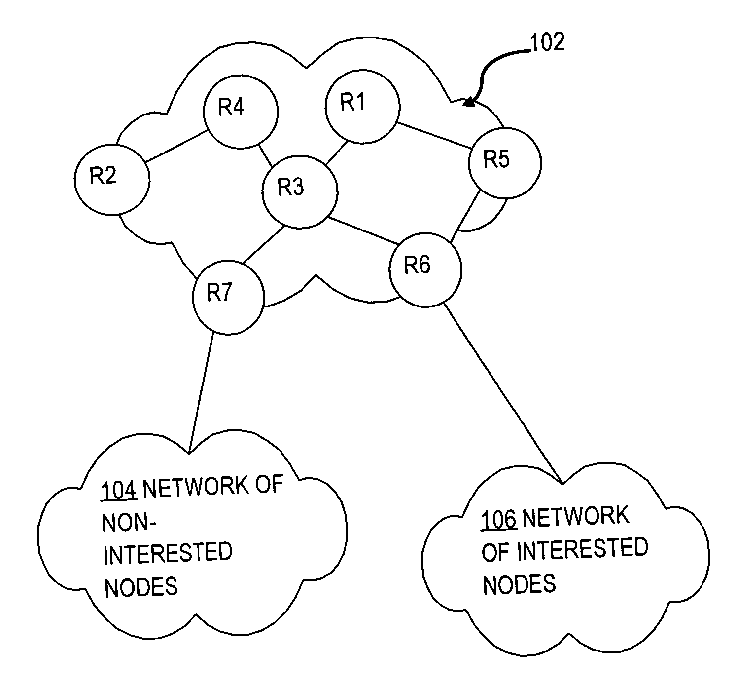
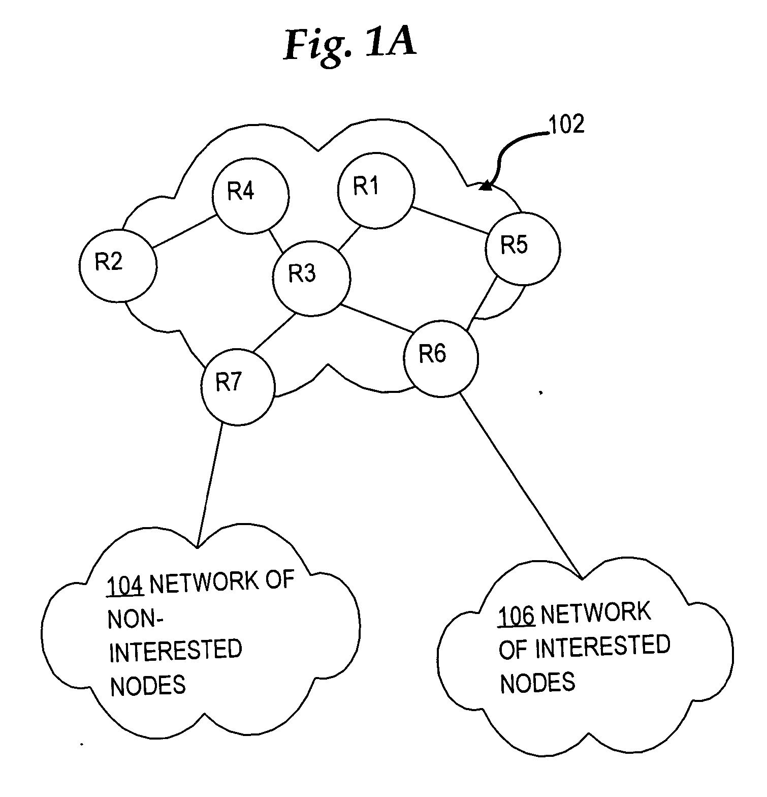
[0022] The needs identified in the foregoing Background, and other needs and obje...


PUM


Abstract

In a link state protocol such as an interior gateway protocol (IGP), link state advertisements or link state packets (LSA/LSPs) are sent only to network nodes that have expressed interest in them, rather than always flooding them.

Description

FIELD OF THE INVENTION [0001] The present invention generally relates to communication of messages in a link state protocol as used by nodes in a network. The invention relates more specifically to techniques for selectively sending link state messages rather than flooding them. BACKGROUND OF THE INVENTION [0002] The approaches described in this section could be pursued, but are not necessarily approaches that have been previously conceived or pursued. Therefore, unless otherwise indicated herein, the approaches described in this section are not prior art to the claims in this application and are not admitted to be prior art by inclusion in this section. [0003] In computer networks such as the Internet, packets of data are sent from a source to a destination via a network of links (communication paths such as telephone or optical lines) and nodes (often routers directing the packet along one or more of a plurality of links connected to it) according to one of various routing protoco...

Claims


Application Information

Patent Timeline
IPC IPC(8): H04L12/28H04L12/56
CPCH04L45/02H04L45/03
Inventor NG, SANDYNALAWADE, GARGILUONG, STEVEN V.
Owner CISCO TECH INC
Why Eureka
Try Eureka