Vacuum cleaner having two cyclonic cleaning stages

a vacuum cleaner and cyclonic technology, applied in the field of vacuum cleaners, can solve the problems of turbulent pressure loss, difficult to clear blockages, increase the cost and complexity of the product manufacturing,

Inactive Publication Date: 2006-06-29
CONRAD WAYNE ERNEST +1
View PDF2 Cites 34 Cited by
  • Summary
  • Abstract
  • Description
  • Claims
  • Application Information

AI Technical Summary

Problems solved by technology

If the blockage occurs at a midpoint of the conduit, it may be difficult to clear the blockage.
Further, the addition of a port increases the cost and complexity of the manufacture of the product.
A bend in a conduit for a fluid causes a turbulent pressure loss in the conduit as the fluid travels through the bend in the conduit and the greater the sharpness of the bend, the greater the pressure loss.
One disadvantage of cyclonic vacuum cleaners is the amount of power which is required to create an air flow sufficient to convey the dirty air through the cyclones at sufficient speeds to maintain the air flowing cyclonically through the cyclones

Method used


Image

  • Vacuum cleaner having two cyclonic cleaning stages
  • Vacuum cleaner having two cyclonic cleaning stages
  • Vacuum cleaner having two cyclonic cleaning stages

Examples


Embodiment Construction

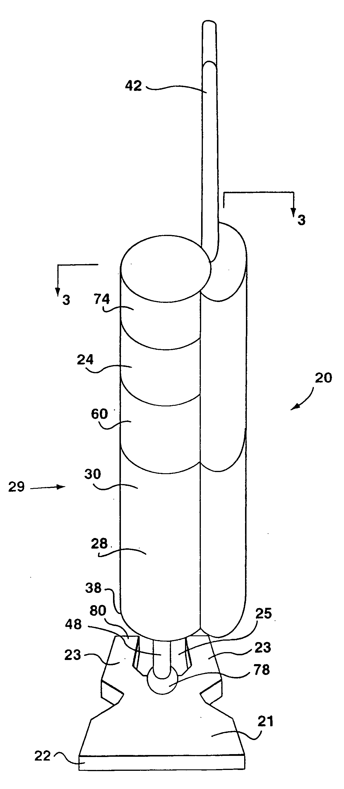
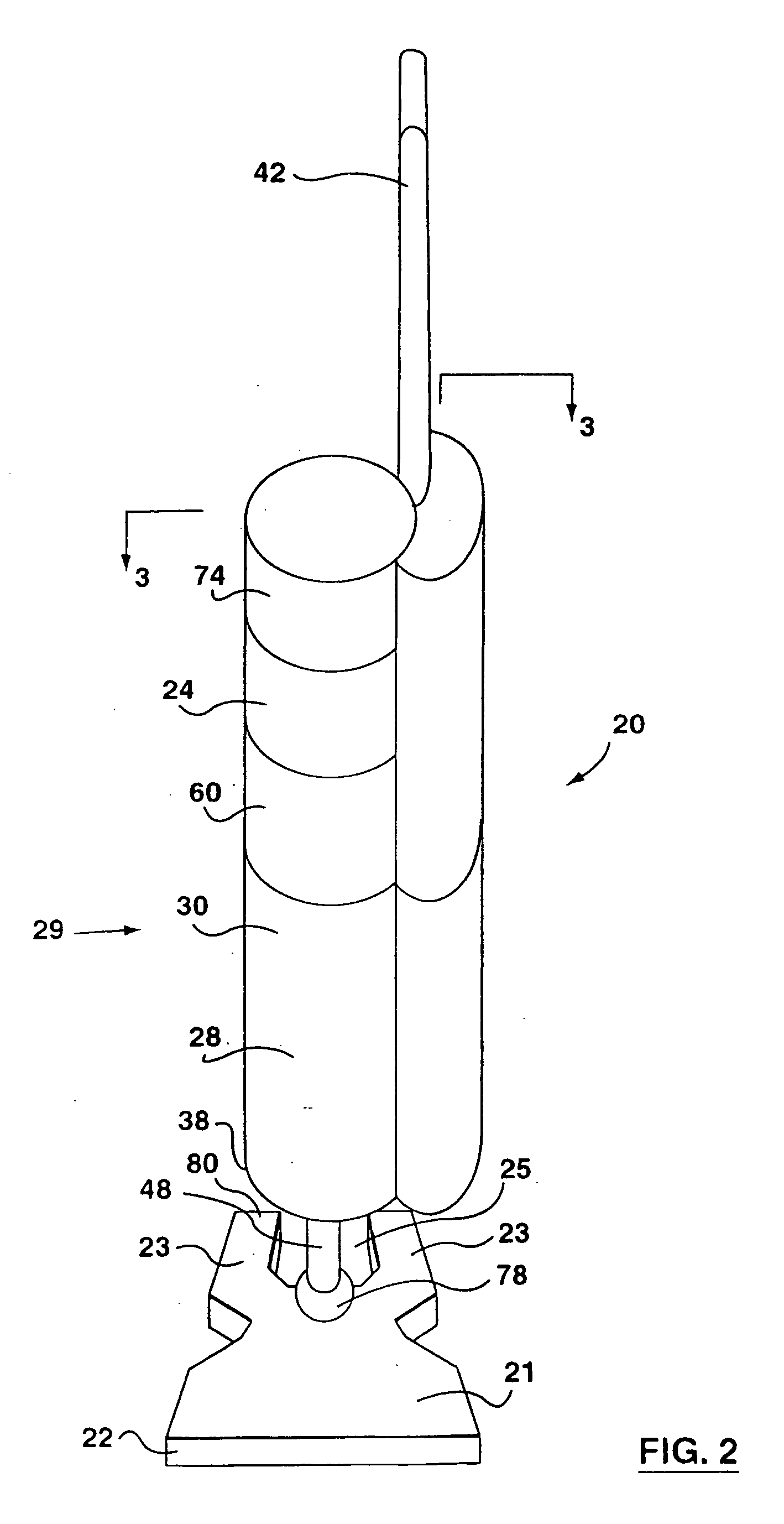
[0048] An upright cyclonic vacuum 20 according to the present invention is shown in the FIGS. 2 and 3. A floor cleaning head 22 is provided at the lower end of vacuum cleaner 20. Head 22 comprises a forward portion 21 and two rear portions 23 extending rearwardly from the forward portion 21. Rear portions 23 are spaced apart and define a space 25 there between. Head 22 has a dirty air inlet 27 which is positioned in forward portion 21 and, preferably, adjacent the front end of forward portion 21 (see FIG. 3). Preferably, head 22 also comprises a transversely extending, floor-contacting rotating brush member 26 which is mounted for rotation in head 22. A handle 42 and rear wheels 44 may be provided on head 22 to facilitate movement of the unit for cleaning of a floor, and the like. Head 22 may also incorporate a forward set of wheels (not shown) as is known in the art.

[0049] In order to be able to convert the vacuum cleaner for above the floor cleaning, handle 42 may be hollow and b...


PUM

PropertyMeasurementUnit
angleaaaaaaaaaa
weightaaaaaaaaaa
weightaaaaaaaaaa

Abstract

A vacuum cleaner has a first and second cyclonic cleaning stages in series. The second cyclonic cleaning stage has a plurality of second stage cyclones. A conduit connects the first cyclonic cleaning stage outlet and the second stage cyclone inlets.

Description

[0001] This application is a continuation of application Ser. No. 11 / 036,609 filed on Jan. 18, 2005 which is a continuation of Ser. No. 10 / 828,250 filed on Apr. 21, 2004 which is a continuation of U.S. patent application Ser. No. 09 / 679,353 filed on Oct. 5, 2000 which is a division of application Ser. No. 09 / 239,860 filed on Jan. 29, 1999 now issued as U.S. Pat. No. 6,334,234, which is a continuation-in-part of application Ser. No. 09 / 227,534 filed on Jan. 8, 1999 now issued as U.S. Pat. No. 6,141,826.FIELD OF THE INVENTION [0002] The present invention relates generally to vacuum cleaners having at least two cyclonic separation stages. BACKGROUND OF THE INVENTION [0003] Various types of vacuum cleaners are traditionally produced. These include built in vacuum cleaners, canister vacuum cleaners and upright vacuum cleaners. Upright vacuum cleaners have a ground engaging portion and an upwardly extending portion. The ground engaging portion typically has wheels for movement of the clea...

Claims


Application Information

Patent Timeline
Patent Type & Authority Applications(United States)
IPC IPC(8): B01D45/12A47L5/28A47L9/00A47L9/16B01D45/16B04C5/02B04C5/103
CPCA47L5/225A47L5/28A47L5/32A47L9/0009A47L9/009A47L9/1625A47L9/1641A47L9/165A47L9/1691B01D45/16B04C5/02B04C5/103B04C5/26B04C5/28B04C9/00B04C2009/002B04C2009/004Y10S55/03
Inventor CONRAD, WAYNE ERNESTCONRAD, HELMUT GERHARD
Owner CONRAD WAYNE ERNEST
Why Eureka
Try Eureka