
Cyclone dust separating apparatus

a technology of cyclone dust separation and separating apparatus, which is applied in the direction of filtration separation, cleaning filter means, separation processes, etc., can solve the problems of deteriorating dust separation efficiency and restricted arrangement of second chambers, so as to improve cleaning efficiency and reduce the loss of suction force

Active Publication Date: 2006-10-19
SAMSUNG GWANGJU ELECTRONICS CO LTD
View PDF20 Cites 118 Cited by
  • Summary
  • Abstract
  • Description
  • Claims
  • Application Information

AI Technical Summary

Benefits of technology

[0009] An aspect of the present invention is to solve at least the above problems and / or disadvantages and to provide at least the advantages described below. Accordingly, an aspect of the present invention is to provide a cyclone dust separating apparatus capable of improving cleaning efficiency by reducing loss of a suction force.
[0010] Another aspect of the present invention is to provide a cyclone dust separating apparatus capable of improving flexibility in design.

Problems solved by technology

However, in the conventional cyclone dust separating apparatus having the above structure, the descending rotary air and the ascending air unavoidably collides with each other in the cyclone chamber because both the air inlet and the air outlet are disposed at the upper part of the cyclone chamber, thereby deteriorating dust separating efficiency of the cyclone dust separating apparatus.
However, because the air inlet and the air outlet of the first cyclone chamber are both disposed at the upper part thereof in the conventional multi-cyclone dust separating apparatus, arrangement of the second chambers is restricted because the second cyclone chambers should not interfere with the air inlet.

Method used


Image

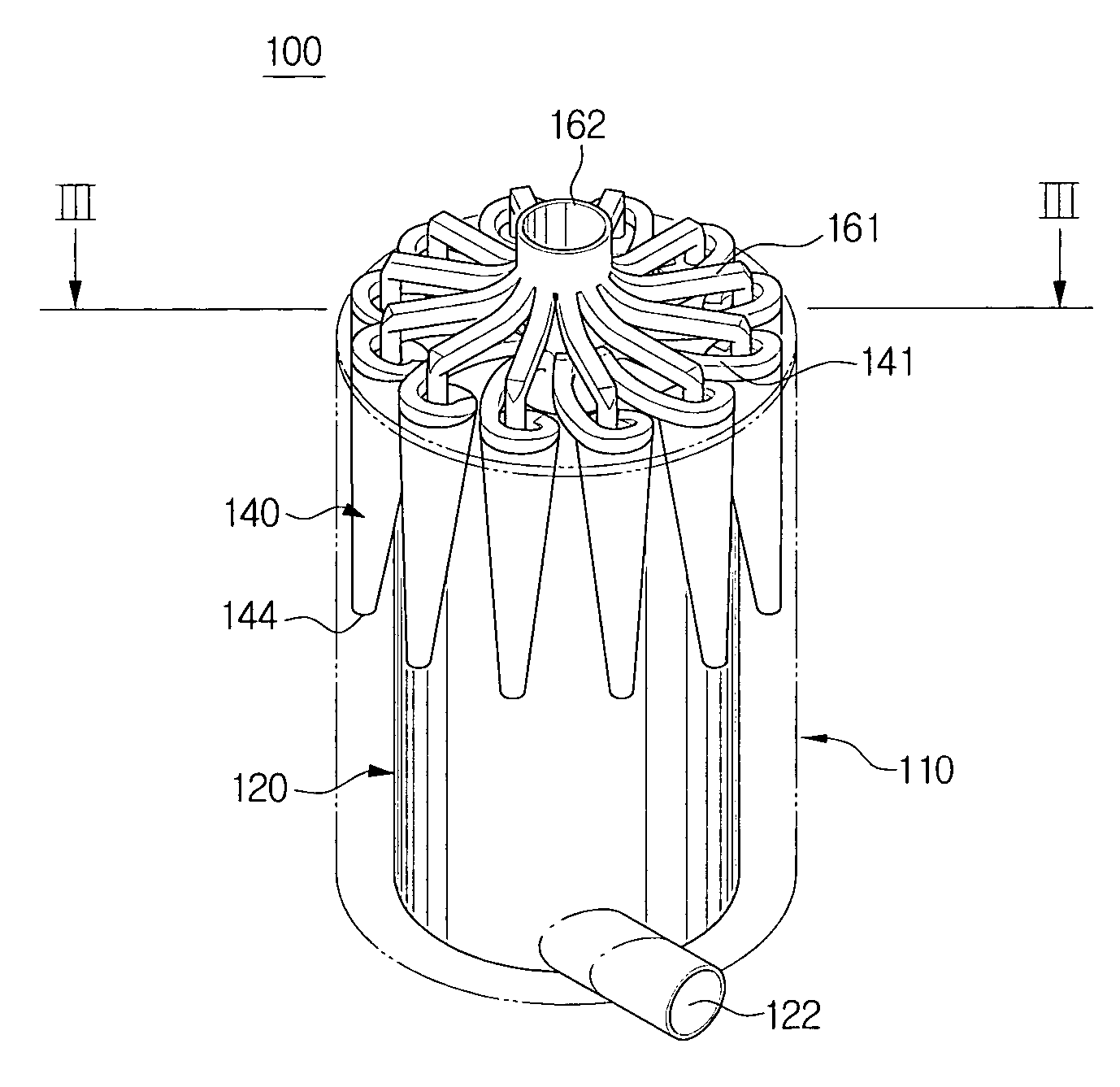
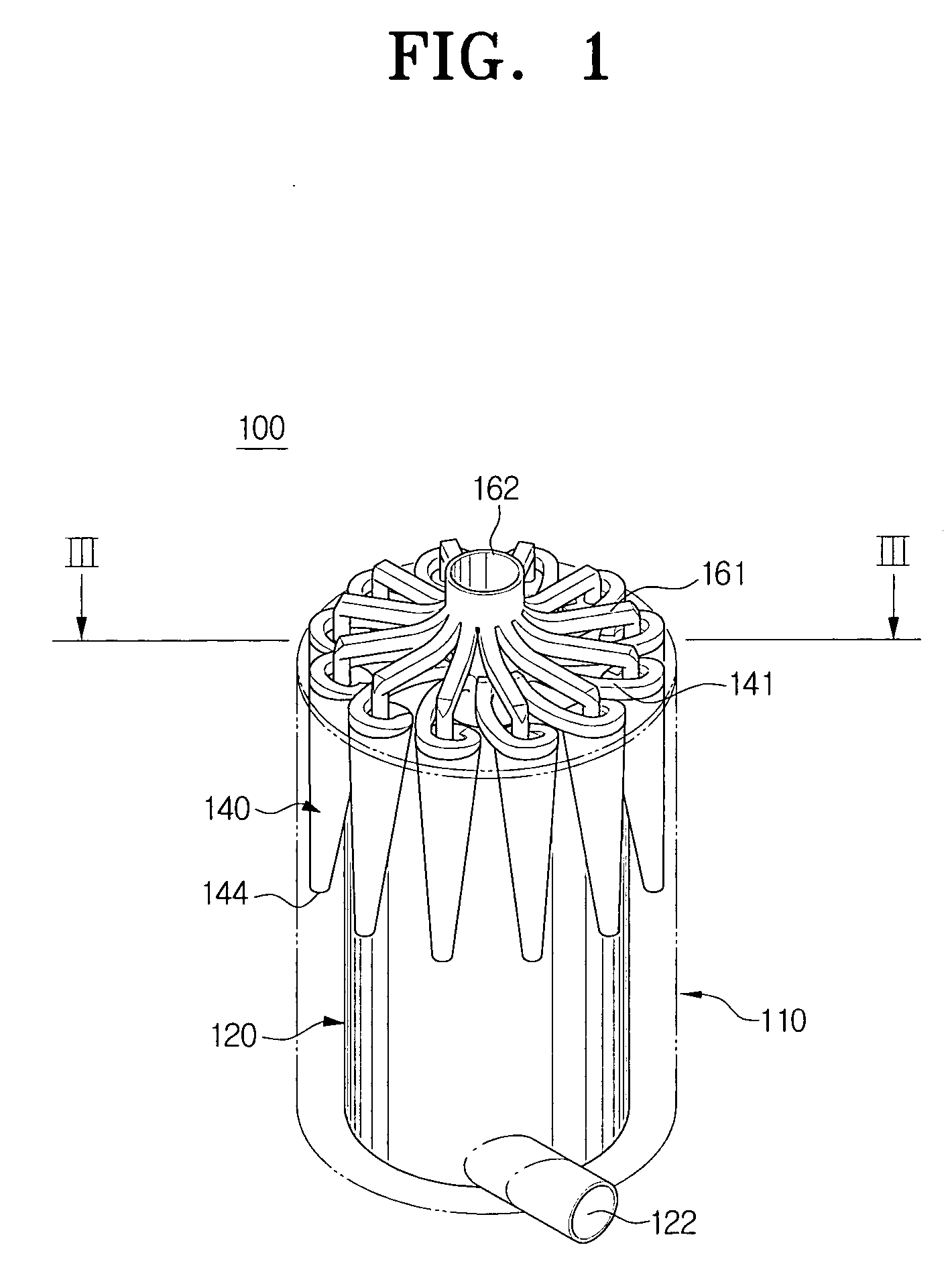
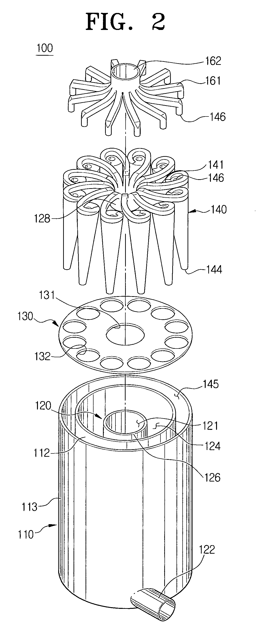
  • Cyclone dust separating apparatus
  • Cyclone dust separating apparatus
  • Cyclone dust separating apparatus

Examples


first embodiment

[0055]FIG. 4 is an exploded perspective view of a vacuum cleaner adopting the cyclone dust separating apparatus 100 according to the present invention. Referring to FIG. 4, the vacuum cleaner according to an embodiment of the present invention comprises the bottom surface brush 101 having the suction port 103, a cleaner body 104 having the driving source 102, a suction path 105 and a discharge path 106, and the cyclone dust separating apparatus 100 removably mounted to a mounting portion 107 of the cleaner body 104.

[0056] The driving source 102 is disposed at a lower part of the cleaner body 104 and may comprise a suction motor for generating the suction force. The suction brush 101 includes the suction port 103 to draw in the dust from a surface being cleaned using the suction force generated by the driving source 102. The suction path 105 is disposed in the cleaner body 104 in fluid communication with the suction port 103 and connected to the first inlet 122 of the cyclone dust se...

second embodiment

[0060] Referring to FIGS. 5 to 7, the cyclone dust separating apparatus 200 according to the present invention comprises a plurality of cyclone chambers. To this end, the cyclone dust separating apparatus 200 comprises a cyclone main body 210, an intermediate cover 270 connected to an upper end of the cyclone main body 210, and an upper cover 250 connected to an upper end of the intermediate cover 270. The cyclone main body 210, the intermediate cover 270, and the upper cover 250 are interconnected through fastening screws (not shown) engaged with fastening holes 211, 271, and 251 which are respectively provided thereto.

[0061] The cyclone main body 210 comprises a first cyclone body 221 constituting the first cyclone chamber 220, and a plurality of second cyclone bodies 231 constituting the second cyclone chamber 230.

[0062] The first cyclone chamber 220 separates the dust from external air drawn in through the suction path 311. For this, the first cyclone chamber 220 is formed insi...


PUM

PropertyMeasurementUnit
Timeaaaaaaaaaa
Diameteraaaaaaaaaa
Radiusaaaaaaaaaa

Abstract

A cyclone dust separating apparatus for separating dust from external air drawn in thereto and discharging the separated dust, comprises at least one first cyclone body having a tubular shape and forming a first cyclone chamber where the external air is rotated; and at least one second cyclone body forming a second cyclone chamber where the air discharged from the first cyclone chamber is rotated again to separate dust, wherein the external air is drawn in through a lower end of the first cyclone chamber and discharged through an upper end of the first cyclone chamber, and the air discharged from the first cyclone chamber is drawn in through an upper end of the second cyclone chamber and discharged through an upper end of the second cyclone chamber.

Description

CROSS-REFERENCE TO RELATED APPLICATIONS [0001] This application claims the benefit of U.S. Provisional Applications No. 60 / 666,143 filed Mar. 29, 2005 and No. 60 / 698,387 filed on Jun. 12, 2005 in the United States Patent and Trademark Office, and claims the benefit of Korean Patent Applications No. 2005-37406 filed on May 4, 2005 and No. 2005-71976 filed on Aug. 5, 2005 in the Korean Intellectual Property Office, the entire disclosures of all of which are incorporated herein by reference.BACKGROUND OF THE INVENTION [0002] 1. Field of the Invention [0003] The present invention relates to a vacuum cleaner. More particularly, the present invention relates to a cyclone dust separating apparatus mounted in a vacuum cleaner to separate dust from air drawn in from a surface being cleaned. [0004] 2. Description of the Related Art [0005] In general cyclone dust separating apparatuses, impurities (hereinafter, referred to as ‘dust’) are separated from external drawn-in air using a centrifugal...

Claims


Application Information

Patent Timeline
IPC IPC(8): B01D45/12
CPCA47L9/1625A47L9/1641A47L9/1666B04C7/00B04C3/06B04C5/185B04C5/28A47L9/1683Y10S55/03
Inventor OH, JANG-KEUNHAN, JUNG-GUYNKIM, MIN-HALEE, HAK-BONG
Owner SAMSUNG GWANGJU ELECTRONICS CO LTD
Learn More