Cyclone dust-collecting apparatus

a dust-collecting apparatus and cyclone technology, applied in auxillary pretreatment, cleaning filter means, separation processes, etc., can solve the problems of increasing volume and weight of multi-cyclone dust-collecting apparatuses, affecting the efficiency of dust collection, so as to achieve low pressure loss and high dust-collecting efficiency

Inactive Publication Date: 2010-04-06
SAMSUNG GWANGJU ELECTRONICS CO LTD
View PDF27 Cites 117 Cited by
  • Summary
  • Abstract
  • Description
  • Claims
  • Application Information

AI Technical Summary

Benefits of technology

[0009]The present disclosure has been developed in order to solve the above described and other problems in the related art. Accordingly, an aspect of the present disclosure is to provide a compact cyclone dust-collecting apparatus having a high dust-collecting efficiency and low pressure loss.
[0018]An air outflow opening of one of the at least two vertical cyclone units may function as an air inflow opening of the other. The at least two vertical cyclone units may include a grill pipe to simultaneously function as an air outflow opening of one of the at least two vertical cyclone units and as an air inflow opening of the other. The grill pipe may include a skirt extending outwards from a bottom end thereof and having a plurality of filter pores to prevent long and thin contaminants capable of being re-scattered, such as hair, from being caught in and blocking the grill pipe.
[0019]One of the at least two vertical cyclone units may fluidly communicate with an air discharge pipe of the horizontal cyclone unit, and the air discharge pipe may include a plurality of guide wings disposed at regular intervals along an outer circumference of the air discharge pipe, so that rotation of air can be accelerated.

Problems solved by technology

A single cyclone dust-collecting apparatus generally includes a single cyclone chamber, but it is impossible for a single cyclone chamber to simultaneously separate dust of different sizes.
However, there is a problem that such multi-cyclone dust-collecting apparatuses increase in volume and weight.
Additionally, if a multi-cyclone dust-collecting apparatus is attached to a cleaner, pressure loss may increase noticeably.
The increase in pressure loss may cause the load on a motor generating a suction force to increase, so it may be impossible to operate the cleaner smoothly.
Furthermore, if dust separated by a cyclone dust-collecting apparatus is re-scattered by air currents, the dust-collecting efficiency may deteriorate.

Method used


Image

  • Cyclone dust-collecting apparatus
  • Cyclone dust-collecting apparatus
  • Cyclone dust-collecting apparatus

Examples


Embodiment Construction

[0030]Hereinafter, a cyclone dust-collecting apparatus according to an exemplary embodiment of the present disclosure will now be described in greater detail with reference to FIGS. 1 to 7.

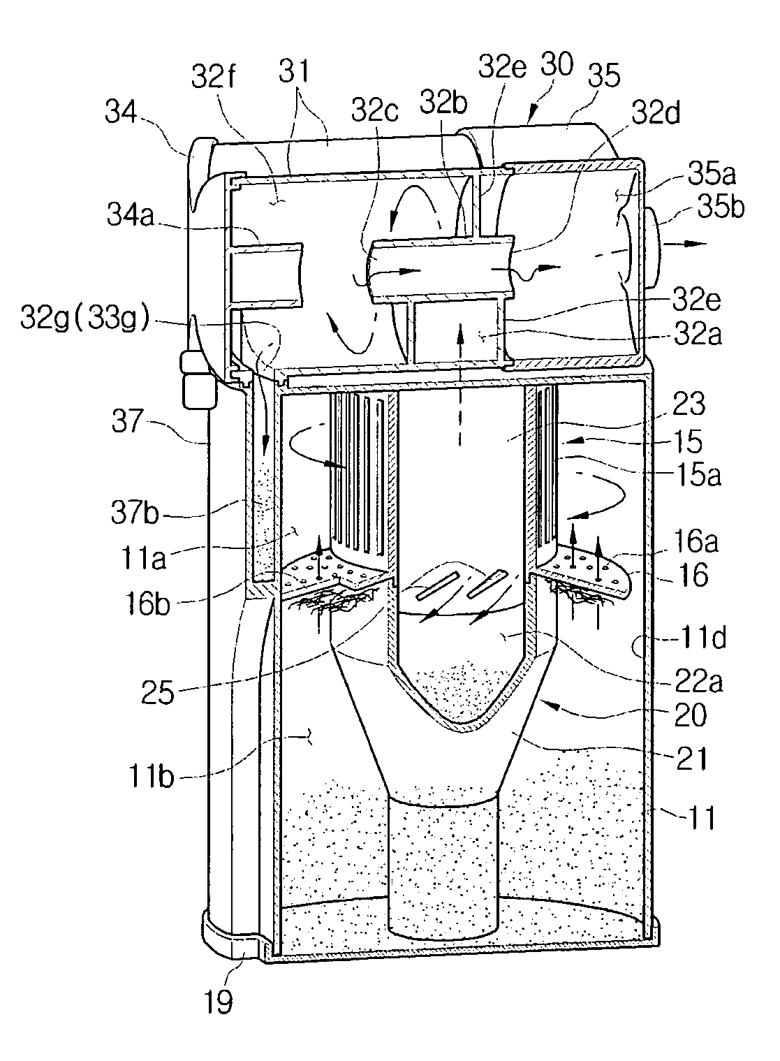
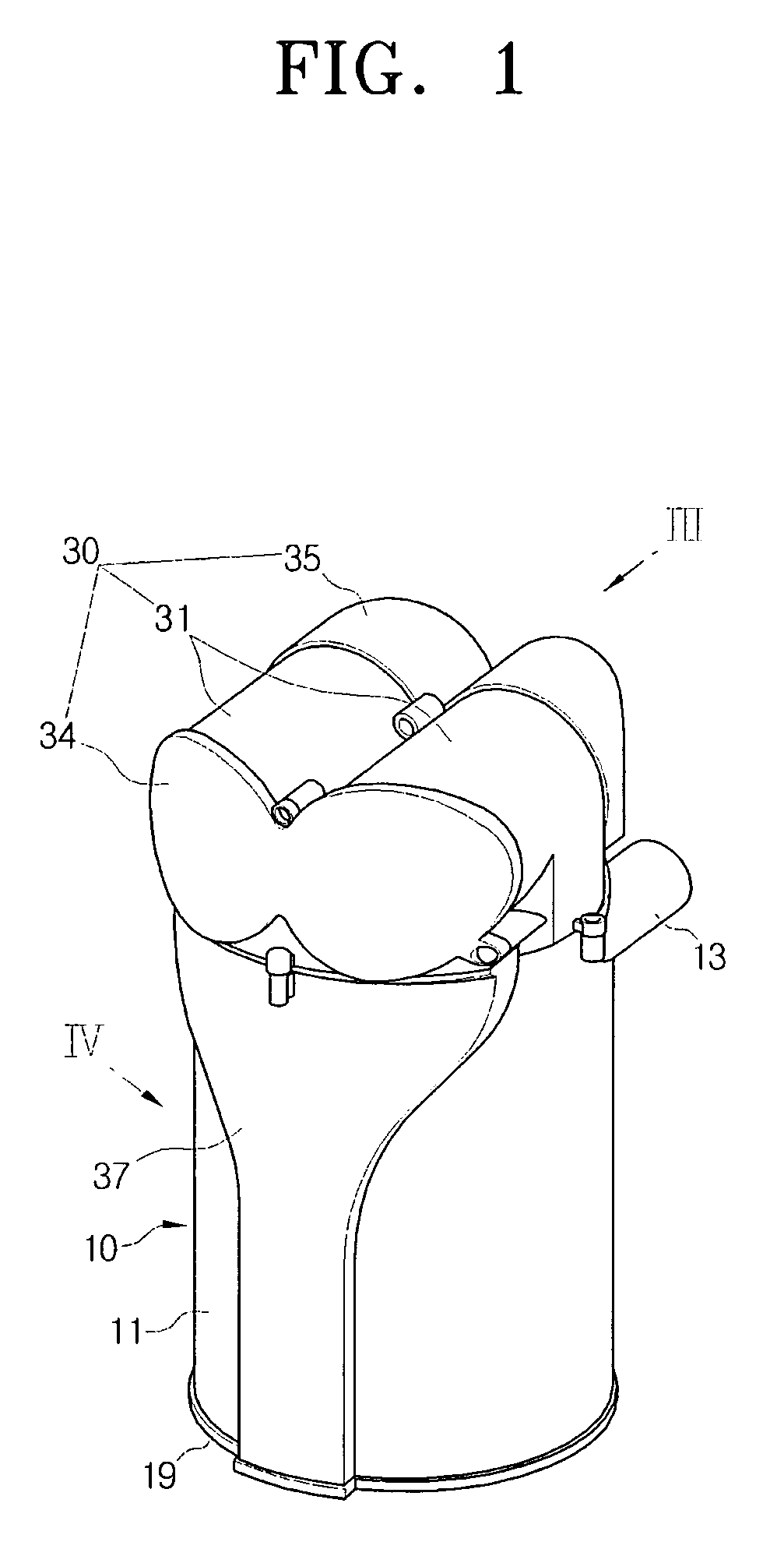
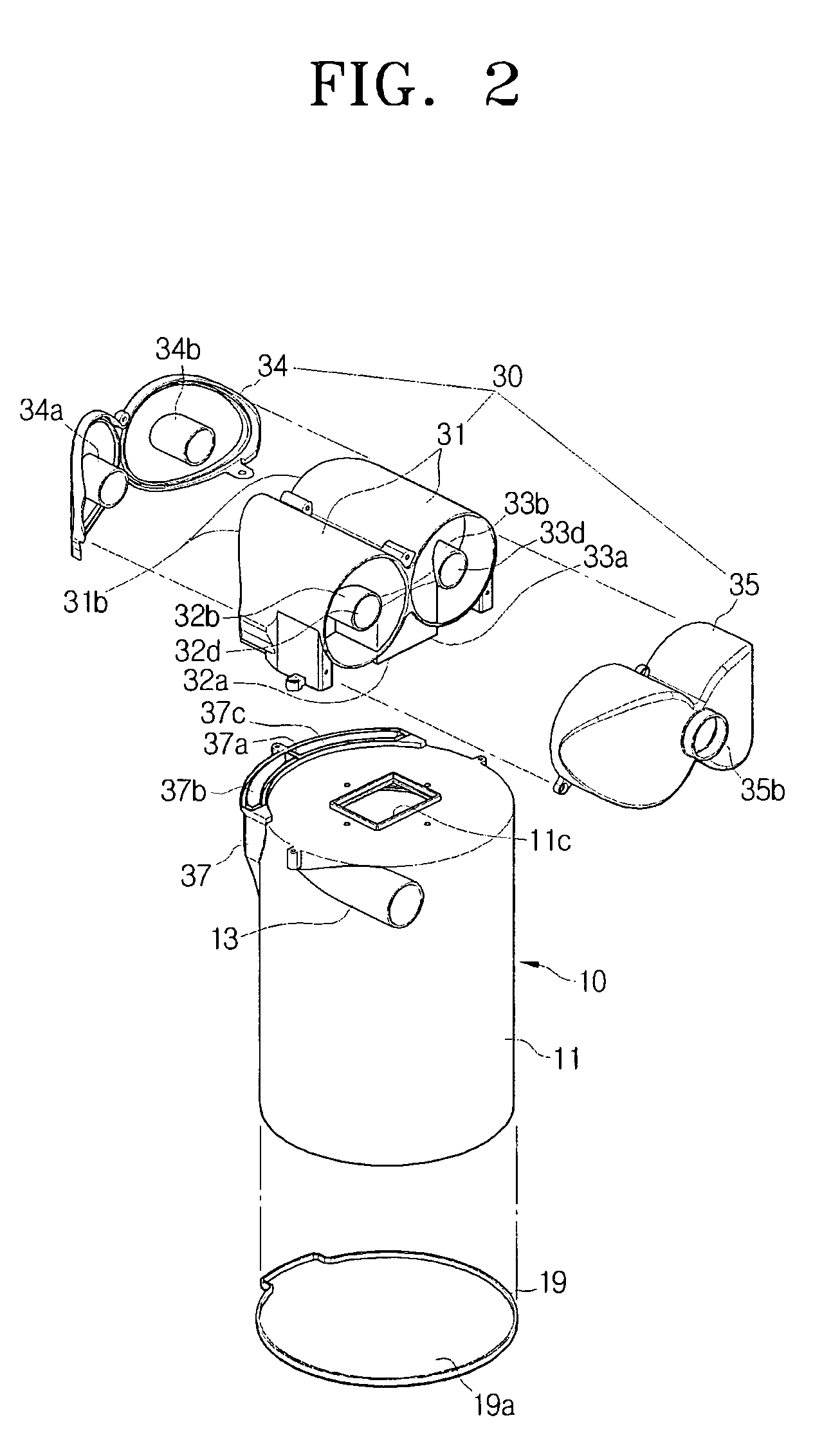
[0031]Referring to FIGS. 1 to 7, a cyclone dust-collecting apparatus is used for a vacuum cleaner (not shown) in order to separate dust drawn into a suction port body (not shown) of the vacuum cleaner from air using a centrifugal force and collect the separated dust. Referring to FIGS. 1, 2 and 5, the cyclone dust-collecting apparatus includes a primary cyclone unit 10, a secondary cyclone unit 20 and a tertiary cyclone unit 30. The primary cyclone unit 10 is disposed vertically overlapping with a secondary cyclone unit 20, and the tertiary cyclone unit 30 is disposed substantially perpendicular to the primary and secondary cyclone units 10 and 20.

[0032]Referring to FIGS. 2 to 7, the primary cyclone unit 10 separates large dust from air drawn into the primary cyclone unit 10 through the suction po...


PUM

PropertyMeasurementUnit
centrifugal forceaaaaaaaaaa
angleaaaaaaaaaa
circumferenceaaaaaaaaaa

Abstract

A cyclone dust-collecting apparatus to separate dust from air drawn in through a suction port body of a vacuum cleaner using a centrifugal force and to collect the separated dust is provided. The cyclone dust-collecting apparatus includes a primary cyclone unit to separate dust from air drawn in through the suction port body; a secondary cyclone unit disposed inside the primary cyclone unit to separate dust from air discharged from the primary cyclone unit; and a tertiary cyclone unit disposed above the primary cyclone unit at an angle different from the primary and secondary cyclone units.

Description

CROSS-REFERENCE TO RELATED APPLICATIONS[0001]This application claims the benefit under 35 U.S.C. §119 of U.S. Provisional Patent Application No. 61 / 063,022, filed on Jan. 31, 2008, in the United States Patent and Trademark Office, and of Korean Patent Application No. 10-2008-25064, filed on Mar. 18, 2008, in the Korean Intellectual Property Office, the entire disclosures of both of which are incorporated herein by reference.BACKGROUND OF THE INVENTION[0002]1. Field of the Invention[0003]The present disclosure relates to a cyclone dust-collecting apparatus, and more particularly, to a cyclone dust-collecting apparatus used for a vacuum cleaner.[0004]2. Description of the Related Art[0005]Vacuum cleaners generally draw in dust-laden air from a surface being cleaned, and filter the dust from the drawn-in dust-laden air using dust-collecting apparatuses housed therein. Cyclone dust-collecting apparatuses generate a centrifugal force by making the drawn-in dust-laden air whirl thereinsid...

Claims


Application Information

Patent Timeline
Patent Type & Authority Patents(United States)
IPC IPC(8): B01D50/00
CPCA47L9/1641A47L9/1633Y10S55/03
Inventor OH, JANG-KEUNCHA, SEUNG-YONG
Owner SAMSUNG GWANGJU ELECTRONICS CO LTD
Why Eureka
Try Eureka