
Dust collecting filter, dust collecting device, and air intake device for gas turbine

Inactive Publication Date: 2006-05-23
MITSUBISHI HITACHIPOWER SYST LTD
View PDF13 Cites 42 Cited by
  • Summary
  • Abstract
  • Description
  • Claims
  • Application Information

AI Technical Summary

Benefits of technology

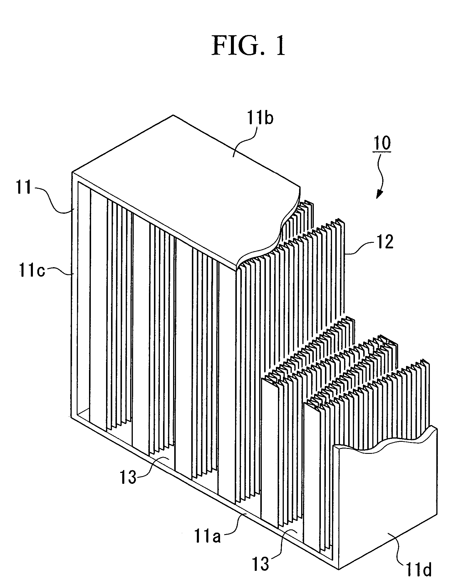
[0014]According to such a dust collecting filter, the upstream non-woven fabric and the downstream non-woven fabric are formed to be a piece of layered filter medium unitarily not only by attaching them simply but also by forming it seamlessly. Therefore, it is possible to form the layered filter medium into a minipleat shape easily. Also, by using such a layered filter medium having a minipleat shape, it is possible to realize a larger filtering area than in a conventional case of a flat layer; therefore, it is possible to maintain a high dust-collecting efficiency for a longer hour under condition of a small size device.
[0059]In such an air intake device for a gas turbine, the dust collecting device is provided with a small size dust collecting filter which can maintain a high dust collecting efficiency; thus, it is possible to realize a small size device. Therefore, the device can be installed in relatively a small space. Also, the dust collecting filter can maintain a high dust collecting efficiency for a longer hours; therefore, it is possible to operate a gas turbine continuously without replacing the dust collecting filter for a longer hours.

Problems solved by technology

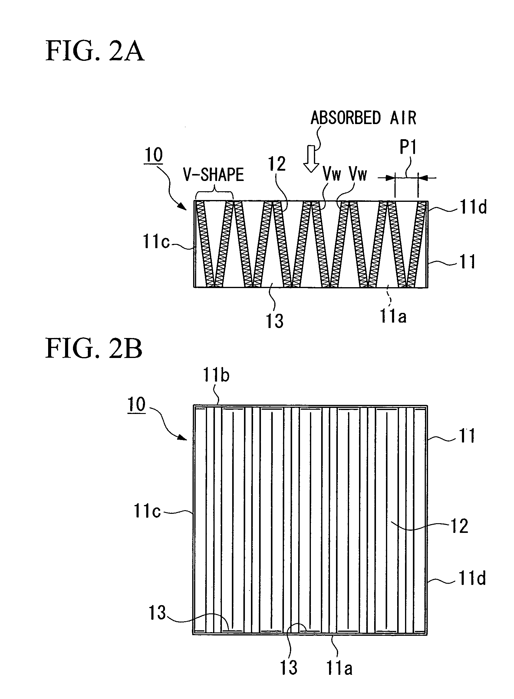
If there are 4 V-shapes or less under such a condition, it is not possible to realize a filtering area as large as 30 m2 to 60 m2.

Method used


Image

  • Dust collecting filter, dust collecting device, and air intake device for gas turbine
  • Dust collecting filter, dust collecting device, and air intake device for gas turbine
  • Dust collecting filter, dust collecting device, and air intake device for gas turbine

Examples


first embodiment

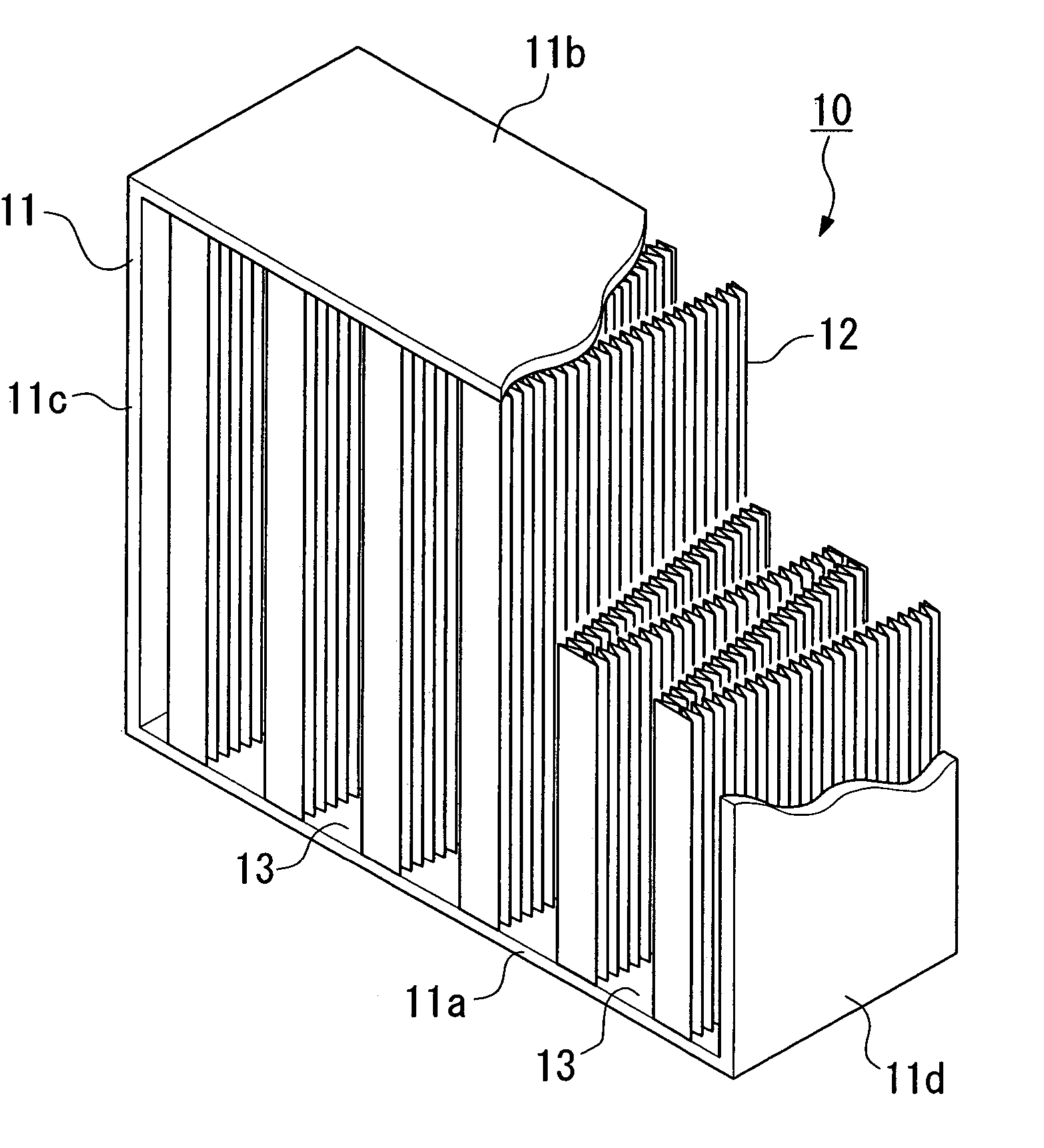
[0075]A dust collecting device has a two-stage structure in which a housing which is connected to the air compressor, a coarse dust collecging filter (pre-filter) which is disposed in an upstream in the housing, and a large capacity HEPA filter (dust collecting filter) which is disposed in a downstream in the coarse dust collecting filter are provided (not shown in the drawing). According to such a dust collecting device, approximately 30% of lithometeors having 1 μm of particle diameter which is absorbed in the housing are removed by passing through the above coarse dust collecting filter. Furthermore, lithometeors having finer particle diameter is collectively removed by passing through the large capacity HEPA filter.

[0076]In the present embodiment, the large capacity HEPA filter is one of the features in the present invention; therefore, explanations are made mainly with regard to this feature.

[0077]As shown in FIGS. 1, 2A, and 2B, the large capacity HEPA filter 10 in the presen...

second embodiment

[0106]Here, FIGS. 7A to 7C show a large capacity HEPA filter which is used in a dust collecting device according to the present invention. FIG. 7A is a plan view of a cross section. FIG. 7B is a back view which is observed from a downstream.

[0107]In the dust collecting device according to the present embodiment, a direction in which a minipleat shape in the layered filter medium 20 (here, reference numeral 20 is add so as to explain independently from the layered filter medium 12) in the large capacity HEPA filter 10 is a feature. That is, in the above first embodiment, a minipleat shape is formed in a direction (direction in which triangular waves occurs in a flowing direction of the absorbed air flow) in which a triangular waves are observed viewed in a plan cross section. In contrast, in the present embodiment, a minipleat shape is formed in a direction (perpendicular direction) in which a triangular waves are observed viewed in a cross section in an orthogonal direction to an ab...


PUM

PropertyMeasurementUnit
Lengthaaaaaaaaaa
Lengthaaaaaaaaaa
Lengthaaaaaaaaaa

Abstract

A large capacity HEPA filter is produced having a layered filter medium unitarily formed by an upstream non-woven fabric, which can remove 70 to 90% of 0.3 μm particles, and a downstream non-woven fabric, which can remove 99.9% of 0.3 μm particles or more. The layered filter medium is shaped as a mini pleat shape in a thickness direction and an entire shape in the thickness direction is a plurality of continuous Vs. Also, a dust collecting device having such a large capacity HEPA filter is produced and an air intake device for a gas turbine is provided with such a dust collecting device.

Description

TECHNICAL FIELD[0001]The present invention relates to, for example, an air intake device for supplying an absorbed air to an air compressing device in a gas turbine, a dust collecting device which is provided to the air intake device for removing lithometeors which are contained in the absorbed air, and a dust collecting filter which is provided in the dust collecting device.BACKGROUND ART[0002]A gas turbine absorbs an atmosphere. Under a normal condition, an atmosphere contains lithometeors having particle diameter of 1 μm to 10 μm Disclosure of Invention. When such a lithometeor is absorbed in a gas turbine and adheres on a rotor blade in an air compressing device, a fluid resistance increases; thus, an output loss increases. As a result, there is a problem in that an electricity generation output decreases. In order to prevent such a problem, as shown in FIG. 10, a dust collecting device 1 (filter unit) is disposed in the air intake device in the gas turbine so as to remove the l...

Claims


Application Information

Patent Timeline
IPC IPC(8): F01D25/00B01D39/16B01D39/20B01D46/00B01D46/10B01D46/52F02C7/052
CPCB01D39/1623B01D39/2017B01D46/0023B01D46/10F02C7/052B01D46/521B01D46/125B01D2275/10B01D2279/60B01D46/62B01D46/121
Inventor KATAYAMA, HIROYUKIDOI, YOSHIYUKIAOTA, TOYOSEIADACHI, TATSUOHARA, SATOSHI
Owner MITSUBISHI HITACHIPOWER SYST LTD
Learn More