

Electric dust collector and method and air supply set using the same
An air supply device and electric dust collection technology, applied in portable electrostatic devices, chemical instruments and methods, botanical equipment and methods, etc., can solve problems such as applied voltage, increased current, and increased power consumption
- Summary
- Abstract
- Description
- Claims
- Application Information
AI Technical Summary
Problems solved by technology
Method used
Image

Examples
Embodiment approach 1
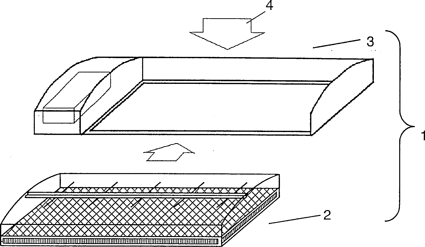
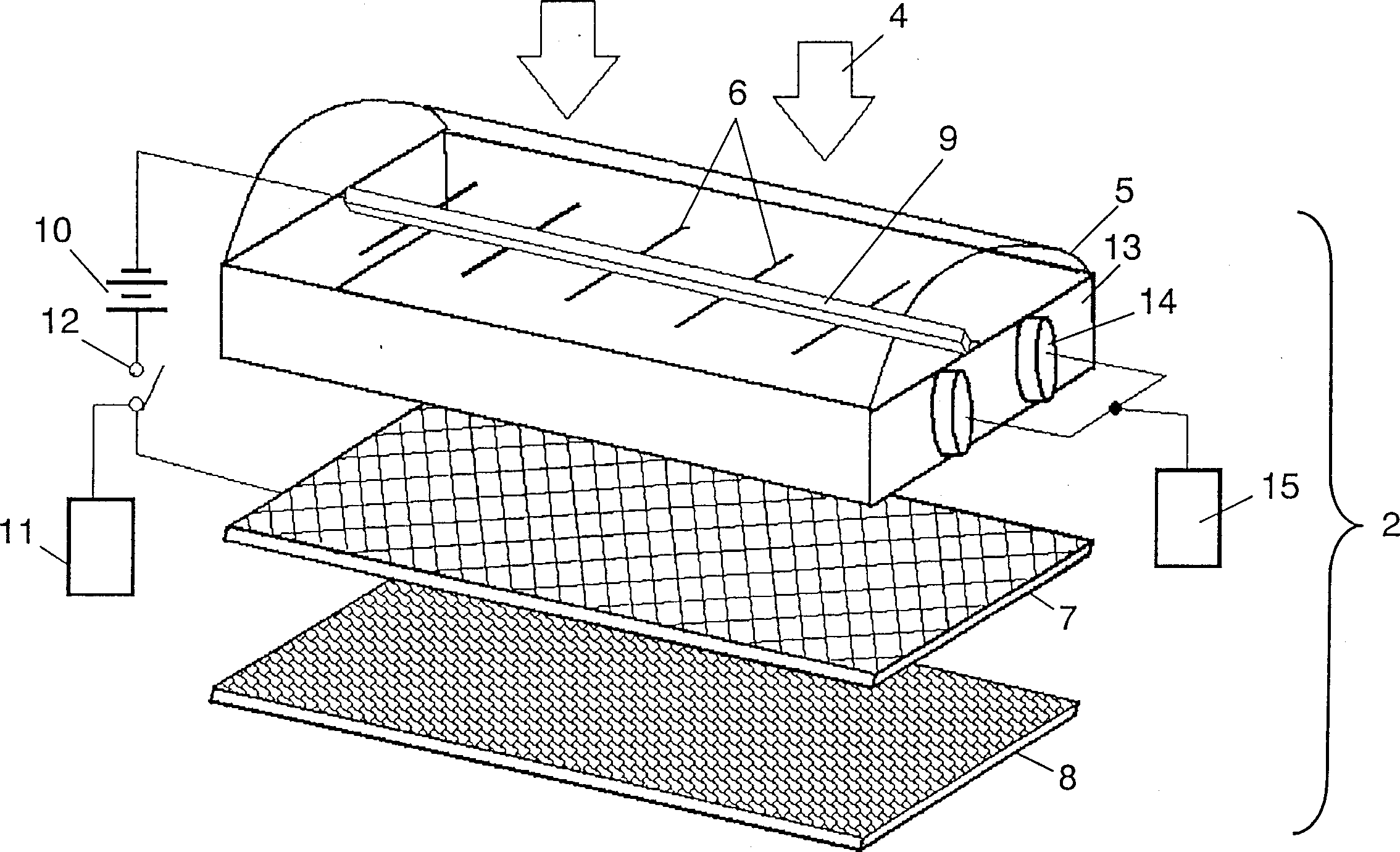
[0020] figure 1 It is an exploded perspective view of the structure of the electrostatic precipitator. figure 2 It is an exploded perspective view of the structure of the dust collecting member of the electric dust collector of this embodiment. Such as figure 1 As shown, the electrostatic precipitator 1 is composed of a dust collecting unit 2 and a main body 3, and the dust collecting unit 2 is accommodated in the main body 3, and installed on an indoor unit of an air conditioner or the like. The indoor air 4 passes through the dust collecting member 2 to collect dust particles contained in the indoor air 4 , and then passes through the heat exchanger of the indoor unit for heat exchange and is blown into the room. Such as figure 2 As shown, the dust collecting member 2 is composed of a casing 5 made of a molded resin material or the like, a discharge electrode 6 , a counter electrode 7 and a dust collecting filter 8 . The casing 5 is formed in a substantially rectangu...
Embodiment approach 2
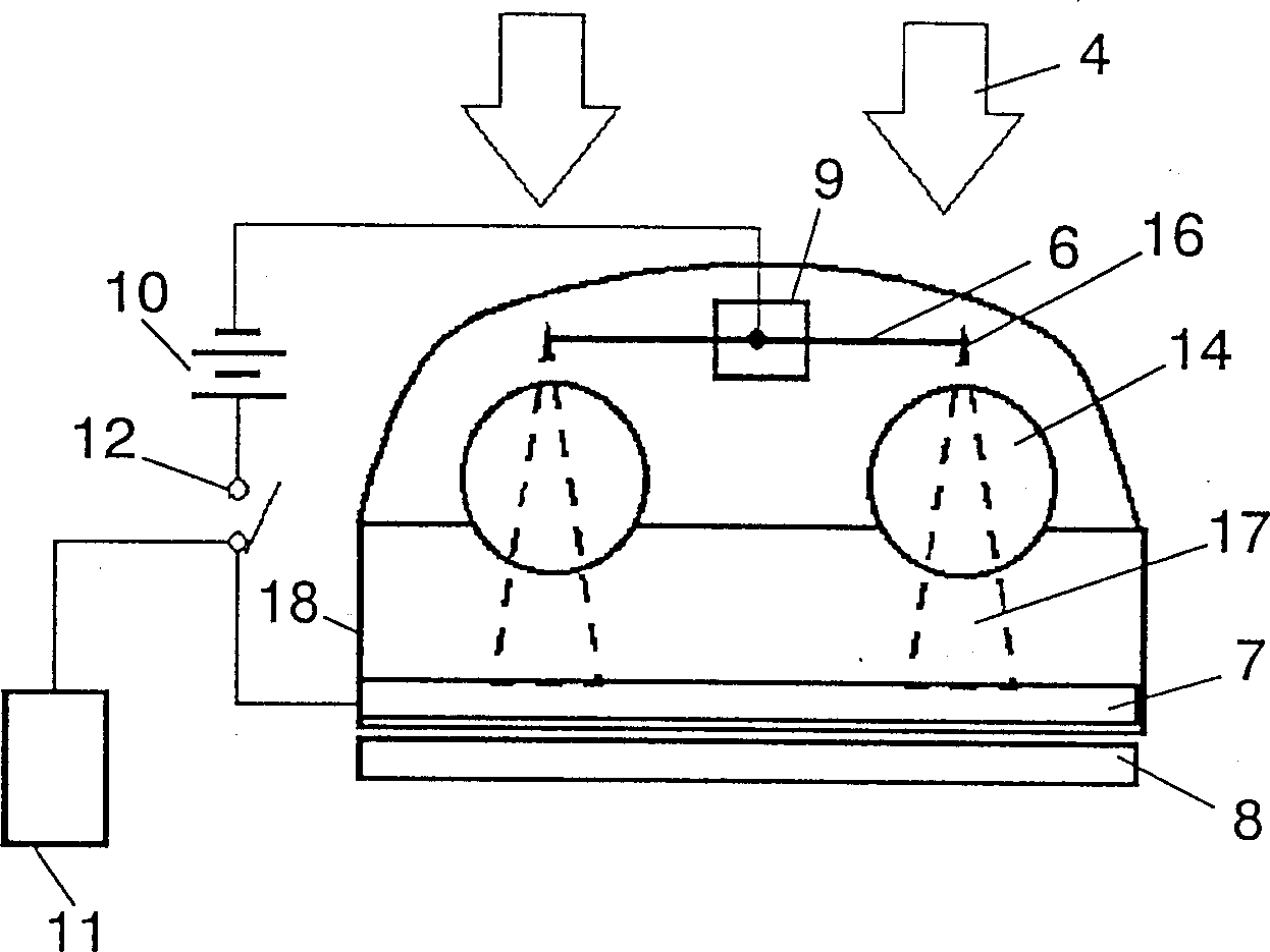
[0037] Use below Figure 5 Embodiment 2 will be described. Components that are the same as those in Embodiment 1 are given the same symbols, and their descriptions are omitted. Figure 5 It is a perspective view showing the structure of the dust collecting member 2 of the electric dust collector according to Embodiment 2 of the present invention.
[0038] In order to take a large suction area of indoor air in equipment such as air conditioners and improve the maintenance of dust collection parts such as cleaning, dust collection parts 2 are divided as shown in the figure and arranged in multiples.
[0039] In the second embodiment of the present invention, the sound wave can be irradiated by the sound wave generating means 14 to such a plurality of dust collecting members 2 . Such as Figure 5 As shown, the sound wave generating mechanism 14 is disposed between the two dust collecting members 2 so that the corona discharge of the both dust collecting members can be irradi...
Embodiment approach 3
[0042] Use below Image 6 Embodiment 3 will be described. Components that are the same as those in Embodiments 1 and 2 are denoted by the same symbols, and descriptions thereof are omitted. Image 6 An exploded perspective view showing the configuration of the dust collecting member 2 according to Embodiment 3 of the present invention.
[0043] The third embodiment differs from the first embodiment in that in the first embodiment, the corona discharge is irradiated with sound waves and diffused, but in the present embodiment, the vibration generating mechanism 20 is arranged so as to vibrate the discharge electrode 6 or the counter electrode 7, Vibration conditions are controlled by the vibration control device 21 . With such a configuration, the corona discharge can be diffused due to the vibration of the discharge electrode 6, and the discharge range can be expanded, that is, the dust collection efficiency can be improved. exist Image 6 In this case, the support body 7 ...
PUM
 Abstract
Description
Claims
Application Information