Air cleaner

An air purification device and air technology, which are applied in the directions of portable electrostatic devices, chemical instruments and methods, power supply technology, etc., can solve the problems such as the reduction of the decomposition efficiency of harmful components and odor components, and achieve the effect of miniaturization

Inactive Publication Date: 2008-01-30
DAIKIN IND LTD
View PDF1 Cites 4 Cited by
  • Summary
  • Abstract
  • Description
  • Claims
  • Application Information

AI Technical Summary

Problems solved by technology

At this time, due to the discharge from the discharge electrode (86a) to other components, the expected streamer discharge does not occur, and thus there may be a problem that the decomposition efficiency of harmful components and odor components in the air to be treated decreases.

Method used


Image

  • Air cleaner
  • Air cleaner
  • Air cleaner

Examples


Embodiment Construction

[0048] Embodiments of the present invention will be described in detail below with reference to the drawings.

[0049] The air cleaning device (10) involved in this embodiment is a civilian air cleaning device generally used in households and small-scale shops. The air purification device (10) removes dust, allergens, odor components, harmful components, etc. in the air to be treated, and purifies the air in an indoor space.

[0050]

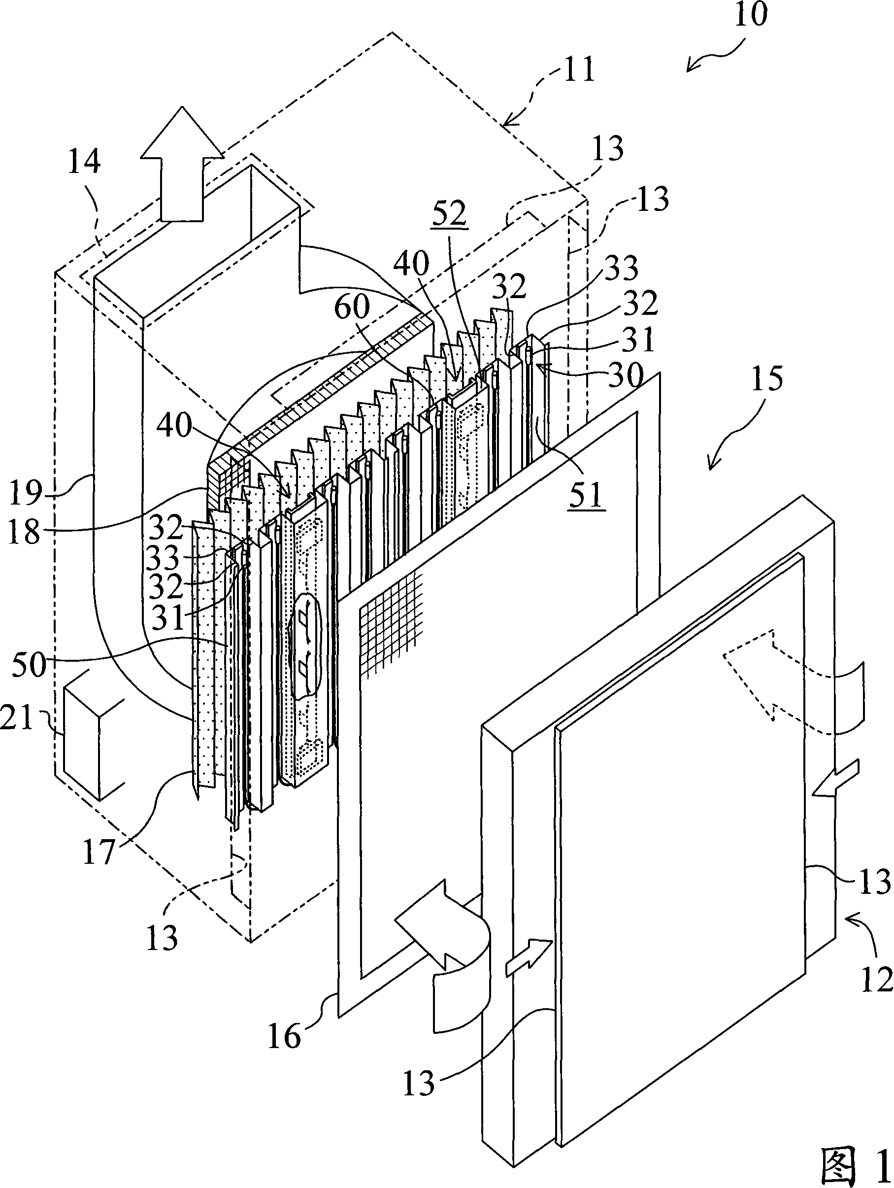
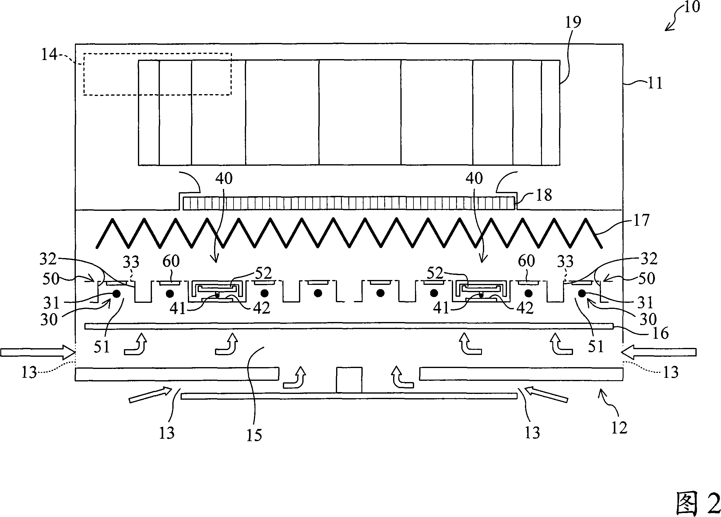
First, the overall configuration of the air cleaning device (10) will be described with reference to Fig. 1 and Fig. 2 . In addition, FIG. 1 is an exploded perspective view of the air cleaning device (10), and FIG. 2 is a view showing the inside of the air cleaning device (10) from above.

[0051] The air cleaning device (10) comprises a box-shaped casing (11) with one end open, and a front baffle (12) installed on the open end surface of the casing (11). An air inlet (13) for introducing indoor air is formed on the left and right side surfac...


PUM

PropertyMeasurementUnit
thicknessaaaaaaaaaa

Abstract

Disclosed is an air purification device including a discharge part for discharging electricity in air. Low-profiling of the air purification device is accomplished while maintaining the discharge capability of the discharge part. In an ionization part (30) for electrically charging airborne dust particles, an insulating medium (60) is disposed between an ionization wire (31) serving as a discharge base end and an earth electrode (33). As a result of such arrangement, electrical discharge from the ionization wire (31) to the earth electrode (33) is obstructed while on the other hand corona discharge from the ionization wire (31) to a first electrode plate (32) is maintained, whereby the distance between the ionization wire (31) and the earth electrode (33) can be made narrow.

Description

technical field [0001] The present invention relates to an air cleaning device including a discharge unit that discharges in the air in which the air to be treated flows. Background technique [0002] Conventionally, air purifiers for purifying the air in indoor spaces such as residences and shops have been known. [0003] For example, in the air cleaning device (80) shown in FIG. 9, an air passage (82) through which the air to be treated flows is formed in the casing (81). In the air passage (82), a pre-filter (83), an ionization part (84), an electrostatic filter (85), a streamer discharge part (86), and a catalyst are sequentially arranged in order from the upstream to the downstream of the air flow. filter (87). [0004] The pre-filter (83) collects relatively large dust in the air introduced into the casing (81). The ionization unit (84) is constituted by a discharge electrode (84a) for electric dust collection and a counter electrode (84b). The discharge electrode ...

Claims


Application Information

Patent Timeline
Patent Type & Authority Applications(China)
IPC IPC(8): B03C3/40B03C3/155B03C3/41B03C3/70A61L9/00A61L9/22
CPCB03C3/70B03C3/41B03C2201/10A61L9/22B03C3/32
Inventor 茂木完治秋山龙司田中利夫香川谦吉
Owner DAIKIN IND LTD
Why Eureka
Try Eureka