
vehicle tire

A tire and vehicle technology, applied in vehicle parts, tire parts, tires, etc., can solve problems such as vehicle electronic equipment failure, and achieve the effect of ensuring discharge performance, improving discharge performance, and improving discharge performance.

Active Publication Date: 2021-06-11
CONTINENTAL REIFEN DEUTSCHLAND GMBH
View PDF20 Cites 0 Cited by
  • Summary
  • Abstract
  • Description
  • Claims
  • Application Information

AI Technical Summary

Problems solved by technology

As a result, failure of vehicle electronics may occur due to sudden voltage discharges

Method used


Image

  • vehicle tire
  • vehicle tire
  • vehicle tire

Examples


Embodiment Construction

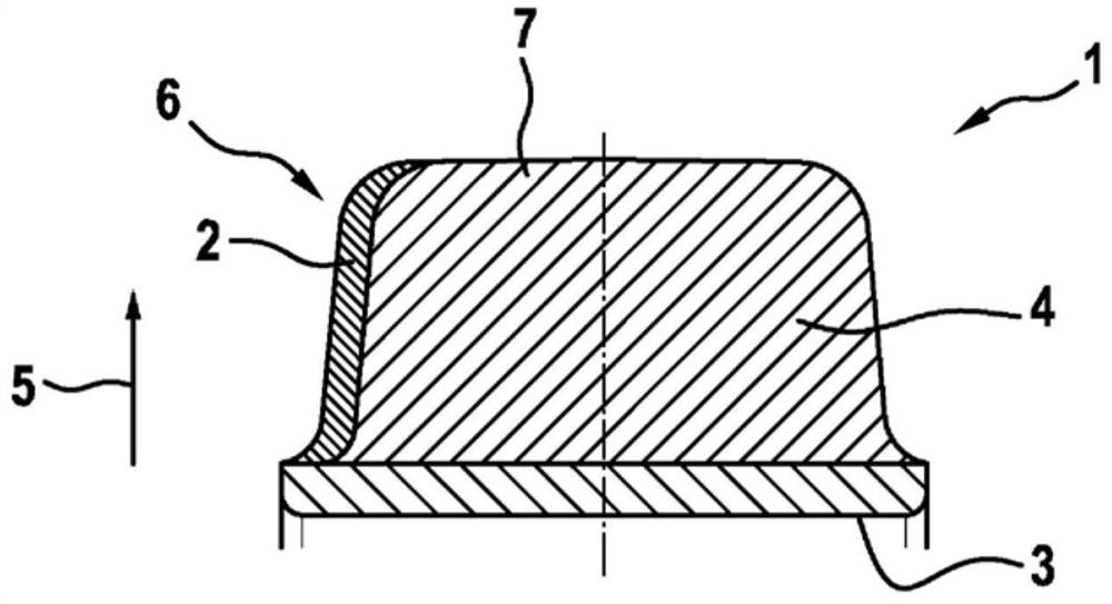
[0017] figure 1 One embodiment is shown. This embodiment is a steel bottom rifle industry tire in a cross-sectional view. In this tire, the bottom conductive tire component is a steel bottom annulus 3. The outer tire part 4 is composed of non-powered and non-conductive rubber mixture, which substantially has a light color color. Side wall members 2 are arranged in the inside of the vehicle tire, which has a conductive rubber mixture with a carbon black material. The side wall member 2 extends from the upper side 7 of the steel bottom sleeve tire 1 until the upper side of the steel bottom annulus 3. Therefore, securely discharged to the lane floor. The case 5 shows the radial direction of the vehicle tire or the solid rubber tire. Embodiments of the tread having two components or rubber mixtures can also be similar to the embodiment of the super-elastic tire.

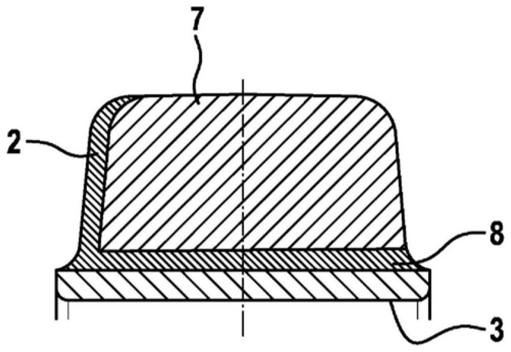
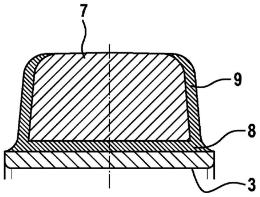
[0018] figure 2 Another embodiment of a steel bottom roller tire is shown. Above the steel bottom wheel 3 arranges a hor...


PUM

PropertyMeasurementUnit
thicknessaaaaaaaaaa

Abstract

In order to provide a vehicle tire in which discharge performance can be ensured in the case of a non-marking solid rubber tire, it is proposed that a side wall part (2) with an electrically conductive rubber compound is arranged on at least one side wall of the vehicle tire , wherein the sidewall part (2) extends from the upper side (7) of the vehicle tire to a bottommost conductive tire part (3, 11) in radial direction (5).

Description

Technical field [0001] The present invention relates to a vehicle tire. Background technique [0002] Land transport vehicles (applied in so-called non-trace rubber applications) typically have a solid rubber tire without conductive. Thereby, the failure of the vehicle electronic device may occur due to sudden voltage discharge. Subsequently, land transport vehicles remain still and must be sent to the maintenance plant in some cases. Inventive content [0003] The basic object of the present invention is to provide a vehicle tire, in particular for land transport vehicles equipped with a seamless solid rubber tire to secure discharge to the lane floor. [0004] According to the preamble and iconic feature of claim 1, the side wall member having a conductive rubber mixture is arranged on at least one side wall of the vehicle tire, wherein the side wall component is from which the side wall member is arranged. The upper side of the vehicle tire extends to a conductive tire member...

Claims


Application Information

Patent Timeline
Patent Type & Authority Patents(China)
IPC IPC(8): B60C7/00B60C19/08B29D30/52
CPCB29D30/02B29D2030/526B60C7/00B60C19/086
Inventor 彼得·施密特马蒂亚斯-斯蒂芬·米勒卡斯滕·明斯尼古拉斯·海因里希斯特芬·霍尔曼
Owner CONTINENTAL REIFEN DEUTSCHLAND GMBH
Learn More