Air processing device

An air treatment device and air treatment technology, which are applied in steam flow control, chemical instruments and methods, electrostatic effect separation, etc., can solve the problems of dirty walls, inability to inhale dust into the shell, and inability to obtain sufficient dust collection performance, etc. achieve the effect of simplifying the composition

Inactive Publication Date: 2013-04-17
DAIKIN IND LTD
View PDF1 Cites 0 Cited by
  • Summary
  • Abstract
  • Description
  • Claims
  • Application Information

AI Technical Summary

Problems solved by technology

[0004] However, in the device of the above-mentioned Patent Document 1, the dust is ionized in the indoor space, so the dust adheres to the walls of the room, etc. before being taken into the electrostatic precipitator of the device, making the walls dirty.
This is the reason for the low dust collection efficiency
[0005] In addition, in the method of diffusing ions in the room to charge the dust as in Patent Document 1, all the charged dust cannot be sucked into the casing, and the dust collection efficiency is lowered, and sufficient dust collection performance may not be obtained.

Method used


Image

  • Air processing device
  • Air processing device
  • Air processing device

Examples


no. 1 approach

[0080] The first embodiment of the present invention will be described.

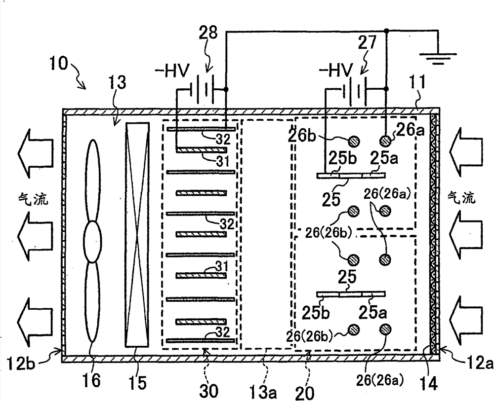
[0081] This first embodiment relates to an air cleaning device 10 as an air processing device according to the present invention. figure 1 It is a sectional view showing a schematic internal structure of the air cleaner 10 .

[0082] The air cleaning device 10 includes a rectangular parallelepiped and hollow housing 11 , and a plurality of functional components are accommodated in the housing 11 . An air suction port 12a is formed on one wall surface of the housing 11, and an air blowing port 12b is formed on a wall surface opposite to the air suction port 12a. The air suction port 12a is provided with a pre-filter 14 for capturing particles having relatively large particle diameters among dust (aerosols) contained in the air to be treated.

[0083] An air passage 13 through which air flows from the air inlet 12a to the air outlet 12b is formed in the casing 11 . In this air passage 13, a charging uni...

Deformed example 1

[0105] In the air cleaning device 10 of the first embodiment, as Figure 4 As shown, in the diffusion space 13a, a diffusion member 13b for diffusing ions into the air may also be provided.

[0106] This diffusion member 13b is composed of a filter member 13b having many fine pores. This filter member 13b has a function of diffusing ions into the air. Therefore, by providing the diffusion member 13b in the diffusion space 13a, the ion diffusion effect of this air cleaning device 10 is improved.

Deformed example 2

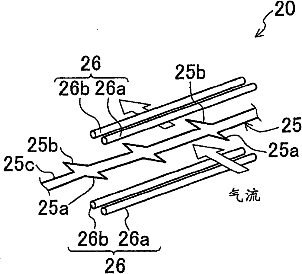
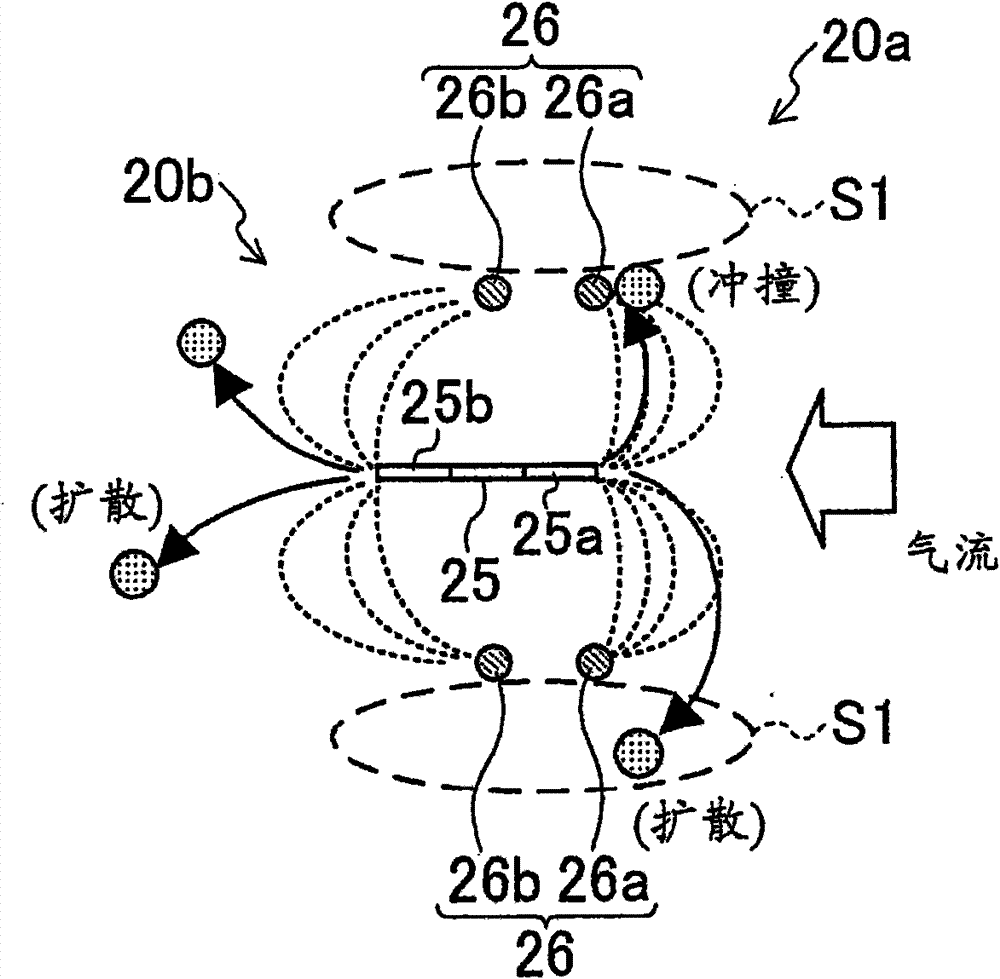
[0108]Modification 2 of the first embodiment, such as Figure 5 As shown, on the discharge electrode 25, an upstream side discharge part 25a (first discharge part 25a) having a first charging part 20a and a downstream side discharge part 25b (second discharge part 25b) having a second charging part 20b are used. In the structure of the zigzag electrode (integrated discharge electrode 25), the opposite electrode 26 of the first electrification part 20a and the opposite electrode 26 of the second electrification part 20b are also formed integrally. Specifically, the opposing electrode 26 is composed of a total of two rod-shaped electrodes arranged one above and the other between the sawtooth-shaped electrodes. The counter electrode 26 is arranged parallel to the discharge electrode 25 on a virtual vertical plane passing through the tip or almost the tip of the upstream side discharge portion 25a. In this configuration, the counter electrode 26 is arranged closer to the first di...


PUM


Abstract

An air handling device (10) includes an air flow path (13) in which a charge section (20) for charging dust in an air to be handled, and a precipitator (30) for collecting the charged dust are placed. The charge section (20) includes a discharge electrode (25) and a counter electrode (26) to perform diffusion charging. A diffusion space (13a) is provided at a location between the charge section (20) and the precipitator (30).

Description

technical field [0001] The present invention relates to an air treatment device which charges and collects dust in the air to be treated, and particularly relates to a technique for improving dust collection efficiency. Background technique [0002] As a conventional air treatment device, Patent Document 1 discloses an air cleaning device in which a main body having an electric dust collecting unit and a charging unit having a charging unit are detachably attached. In this air purifier, the dust is charged by releasing ions generated in the charging unit into the room to combine with the dust floating in the air, and this dust is sucked by the fan of the air purifier body and collected by the electric dust collection unit . [0003] Patent Document 1: Japanese Laid-Open Patent Publication No. 2006-116492 [0004] However, in the device of Patent Document 1, the dust is ionized in the indoor space, so the dust adheres to the walls of the room or the like before being taken ...

Claims


Application Information

Patent Timeline
Patent Type & Authority Patents(China)
IPC IPC(8): B03C3/40B03C3/36B03C3/41
CPCB03C3/383B03C3/41B03C3/155B03C2201/10B03C2201/04B03C3/08B03C3/011B03C3/361B03C3/45B03C2201/06B03C2201/08
Inventor 田中利夫春名俊治茂木完治秋山竜司
Owner DAIKIN IND LTD
Why Eureka
Try Eureka