Multi cyclone dust collector for a vacuum cleaner

a vacuum cleaner and dust collector technology, applied in the field of vacuum cleaners, can solve the problems of high height and decreased dust collection efficiency of dust collectors, and achieve the effect of convenient us

Inactive Publication Date: 2009-06-16
SAMSUNG GWANGJU ELECTRONICS CO LTD
View PDF11 Cites 46 Cited by
  • Summary
  • Abstract
  • Description
  • Claims
  • Application Information

AI Technical Summary

Benefits of technology

[0015]Another object of the present invention is to provide a multi-cyclone dust collector that has a high dust collecting efficiency and a long filter maintenance cycle because collected contaminants are not re-scattered.
[0056]Furthermore, with the multi-cyclone dust collector according to embodiments of the present invention, it is convenient for a user to see the quantity of contaminants collected in a first dust collecting chamber without opening an upper cover. Also, it is convenient for a user to empty contaminants collected in the first and second dust collecting chambers because the user can dump out contaminants by opening the upper cover and turning the first and second dust collecting chambers upside down.

Problems solved by technology

Accordingly, the conventional cyclone dust collector 500 has a problem that a dust collecting efficiency thereof is decreased due to collision between the rising air and the descending air.
Furthermore, the conventional multi-cyclone dust collector 600 has a drawback that the height thereof is high, because the space in which the air whirls and the space in which contaminants are collected are arranged vertically.

Method used


Image

  • Multi cyclone dust collector for a vacuum cleaner
  • Multi cyclone dust collector for a vacuum cleaner
  • Multi cyclone dust collector for a vacuum cleaner

Examples


first embodiment

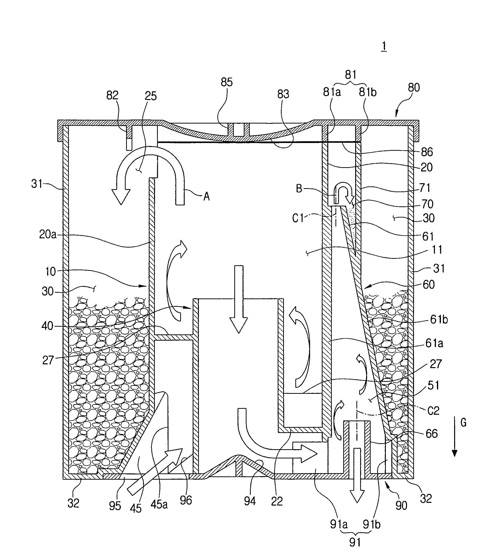
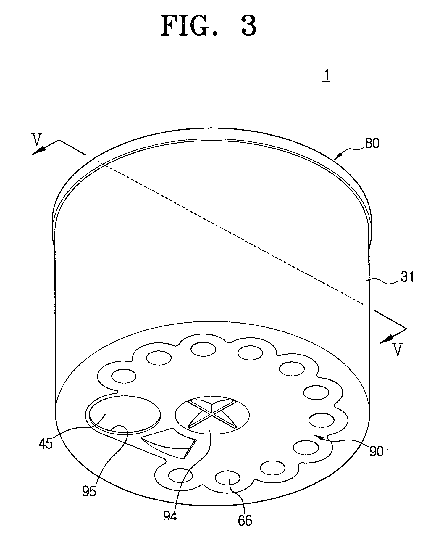
[0077]Referring to FIGS. 3 to 5, a multi-cyclone dust collector 1 for a vacuum cleaner of the present invention includes a first cyclone 10, a first dust collecting chamber 30, and a second cyclone unit 50.

[0078]The first cyclone 10 employs at least one cyclone, and takes in air that is sucked through a suction brush 110 (see FIG. 15) and contains contaminants and dust (hereinafter, referred to as a contaminants-laden air). The first cyclone 10 forces the air to enter into a lower portion of the first cyclone 10 and to whirl upwardly so as to separate contaminants from the contaminants-laden air by centrifugal force operating upon the whirling contaminants-laden air current. In other words, the first cyclone 10 forms the contaminants-laden air entering in a direction opposite to the gravity direction (in a direction opposite to arrow G in FIG. 5) through the lower portion thereof into a first upwardly whirling air current, so that the first cyclone 10 centrifugally separates contam...

second embodiment

[0102]The contaminants-laden air flowing to the multi-cyclone dust collector 1 is entered into a lower portion of the first cyclone body 20 through the air suction pipe 45. The contaminants-laden air sucked into the first cyclone body 20 forms the first upwardly whirling air current that whirls upwardly inside the first cyclone body 20. At this time, the contaminants-laden air entering the lower portion of the first cyclone body 20 easily forms the first upwardly whirling air current due to the sloping surface 27 disposed before the exit 45a of the air suction pipe 45 on the bottom surface 22 of the first cyclone body 20. Then, contaminants are separated from the contaminants-laden air by the centrifugal force operating upon the first upwardly whirling air current. The separated contaminants are moved in a direction opposite to the gravity direction (in a direction opposite to arrow G), and then are discharged to the first dust collecting chamber 30 over the top end of the first cyc...

third embodiment

[0110]Hereinafter, a multi-cyclone dust collector 3 for a vacuum cleaner of the present invention will be explained in details referring to FIGS. 12 and 13.

[0111]Referring to FIGS. 12 and 13, a multi-cyclone dust collector 3 for a vacuum cleaner according to third embodiment of the present invention includes a first cyclone 310, a first dust collecting chamber 330, a plurality of second cyclones 360, and a plurality of second dust collecting chambers 370.

[0112]The first cyclone 310 is disposed at a substantially center of the multi-cyclone dust collector 3, and sucks contaminants-laden air, which are sucked through a suction brush 110 (see FIG. 15), into a lower portion of the first cyclone 310 in a direction opposite to the gravity direction (in a direction opposite to arrow G). The first cyclone 310 forces the contaminants-laden air to whirl upwardly inside the first cyclone 310 so as to form a first upwardly whirling air current and to separate contaminants from the contaminants...


PUM

PropertyMeasurementUnit
sizeaaaaaaaaaa
gravityaaaaaaaaaa
heightaaaaaaaaaa

Abstract

A multi-cyclone dust collector including at least one first cyclone forcing contaminants-laden air that is entered into a lower portion of the at least one first cyclone to whirl so as to centrifugally separate contaminants from the contaminants-laden air; and at least one second cyclone being disposed around the at least one first cyclone, the at least one second cyclone forcing semi-clean air that is discharged from the at least one first cyclone and is entered into a lower portion of the at least one second cyclone to whirl so as to centrifugally separate fine contaminants from the air.

Description

CROSS-REFERENCE TO RELATED APPLICATIONS[0001]This application claims the benefit under 35 U.S.C. § 119(a) of U.S provisional application No. 60 / 725,609, filed Oct. 11, 2005, in the United States Patent & Trademark Office, and claims the benefit of Korean Patent Application No. 2005-102615, filed Oct. 28, 2005, and No. 2006-11668, filed Feb. 7, 2006, in the Korean Intellectual Property Office, the disclosure of each of the above-listed applications are incorporated herein by reference.BACKGROUND OF THE INVENTION[0002]1. Field of the Invention[0003]The present invention relates to a vacuum cleaner. More particularly, the present invention relates to a multi-cyclone dust collector for a vacuum cleaner that separates and collects contaminants from sucked air by centrifugal force.[0004]2. Description of the Related Art[0005]A cyclone type vacuum cleaner, which separates contaminants from sucked air by centrifugal force, employs a cyclone dust collector providing semi permanent use. Becau...

Claims


Application Information

Patent Timeline
Patent Type & Authority Patents(United States)
IPC IPC(8): B01D45/12
CPCA47L9/1625A47L9/1641A47L9/165A47L9/1658A47L9/1683B01D45/12B01D45/16B04C5/13B04C5/185B04C5/26B01D2273/28Y10S55/03E03C1/26B65F1/16B65F1/1405B09B3/00B09B2101/02
Inventor OH, JANG-KEUNHAN, JUNG-GYUNKIM, TAK-SOO
Owner SAMSUNG GWANGJU ELECTRONICS CO LTD
Why Eureka
Try Eureka