Whirlwind hand-held type vacuum dust collector

A vacuum cleaning, hand-held technology, applied in the direction of suction filters, etc., can solve the problem of different particle sizes

Inactive Publication Date: 2007-10-31
KWONNIE ELECTRICAL PRODS
View PDF4 Cites 118 Cited by
  • Summary
  • Abstract
  • Description
  • Claims
  • Application Information

AI Technical Summary

Problems solved by technology

However, the design also has practical disadvantages due to t

Method used


Image

  • Whirlwind hand-held type vacuum dust collector
  • Whirlwind hand-held type vacuum dust collector
  • Whirlwind hand-held type vacuum dust collector

Examples


Embodiment Construction

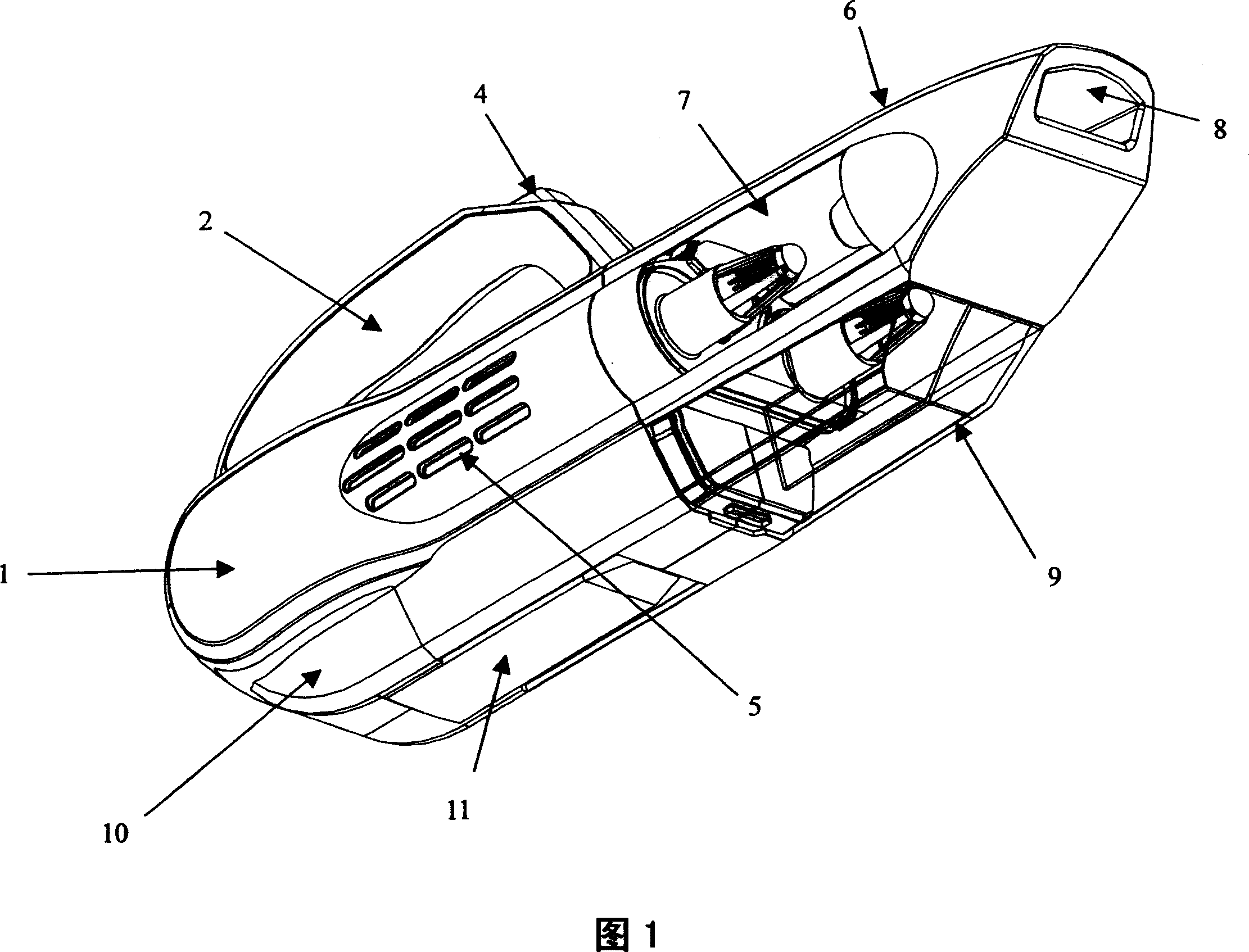
[0026] As shown in FIG. 1 , the vacuum cleaner mainly includes a main housing 1 and a dust cup 6 . The dust cup 6 forms part of the vacuum cleaner body when connected to the main housing 1 . The upper part of the main housing 1 is a handle 2 including a dust cup release button 4 , the air inlet passage opening 8 is located at the front end of the dust cup 6 , and the bottom part of the dust cup 6 forms a dust collection chamber 9 . In a preferred embodiment, the dust collection chamber 9 is made of a transparent material so that the amount of dust collected inside can be observed. A removable battery cover 10 is attached to the rear bottom portion of the main housing 1 to facilitate removal of the battery for recycling or repair purposes. The accessories 11 can be stored on the underside of the main housing 1 when not in use. Both sides of the main housing 1 have slits 5 serving as exhaust gas outlets. A cyclone body 7 is located in the dust cup 6 and forms part of the surf...


PUM


Abstract

The invention discloses a chargeable hand-held vacuum aspirator, which is characterized by the following: possessing mounting or dismounting dust cup section; setting the dust cup as two parallel cyclones and two collecting dust chamber; connecting the collecting dust chamber to the cyclone body; using smaller cyclone because of two parallel cyclones; realizing better dust separating property; setting the cyclone body without filter and collecting dust chamber; increasing cyclone action efficiency with the two parallel cyclones; needing very simple filter; protecting blade wheel in the aspirator. This invention does not appear gradually clogging situation.

Description

technical field [0001] The present invention relates to a rechargeable hand-held vacuum cleaner, and more particularly to a rechargeable hand-held vacuum cleaner using a parallel cyclone as a separation device. Background technique [0002] A typical handheld vacuum cleaner has a motor connected to an impeller, which can be powered by mains power or a rechargeable battery, and which creates an airflow that passes through the nozzle, through the dust cup and into the impeller . Inside the dust cup, most will be provided with a simple filter, sometimes applied in conjunction with the cyclonic movement of the air, to separate dirt and dust from the air. Another filter can be placed after the impeller to filter fine dust or carbon dust from the motor before the exhaust air exits the vacuum cleaner. [0003] One problem with typical handheld vacuums that have a simple filter in the dust cup is that when the filter receives too much dust, the filter can quickly become clogged, r...

Claims


Application Information

Patent Timeline
IPC IPC(8): A47L9/16
Inventor 何稼楠
Owner KWONNIE ELECTRICAL PRODS
Why Eureka
Try Eureka