Sheet shutter

Inactive Publication Date: 2006-07-06
SANWA HLDG CORP
View PDF7 Cites 40 Cited by
  • Summary
  • Abstract
  • Description
  • Claims
  • Application Information

AI Technical Summary

Benefits of technology

[0007] According to the invention of claim 2, in claim 1, the second guide body is formed to be longer in the vertical direction than the pitch of the fitting pieces. With this construction, the guidance of the fitting piece to the opposing site to the rail groove can be further reliably carried out.
[0025] According to the invention of claim 10, the urging force can be strengthened without increasing the space of the guide rail. Therefore, the user range of the sheet shutter device can be enlarged, and also the degree of freedom of adjusting the urging force can be improved.

Problems solved by technology

In this type of sheet shutter device, because the shutter curtain is formed of a sheet member having flexibility, the shutter curtain is greatly deformed when a large wind blast or a load from an obstruction is applied thereto, so that the guide rail or shutter curtain may be damaged.
The structure described above requires work of returning the temporarily-disengaged engaging pieces to the rail grooves again, however, this work is not only cumbersome and troublesome, but also requires an overhead working.
In the conventional shutter device, the end portions of the bone members as well as the engaging pieces are engagedly fitted in the rail grooves and thus the opening / closing sound is intense, the rail grooves are liable to be worn because the end portions of the bone members are in friction with the rail grooves, and also the magnitude of the load when the fitting pieces slip out of the rail grooves varies with time lapse.
Furthermore, when the fitting pieces getting out of the rail grooves are automatically restored into the rail grooves, a plurality of bone-member end portions continuously and strongly abut against the auxiliary guides, so that the abutting sound is intensified and thus ambient noise occurs.

Method used


Image

  • Sheet shutter
  • Sheet shutter
  • Sheet shutter

Examples


first embodiment

[0049] A first embodiment according to the present invention is described with reference to the drawings.

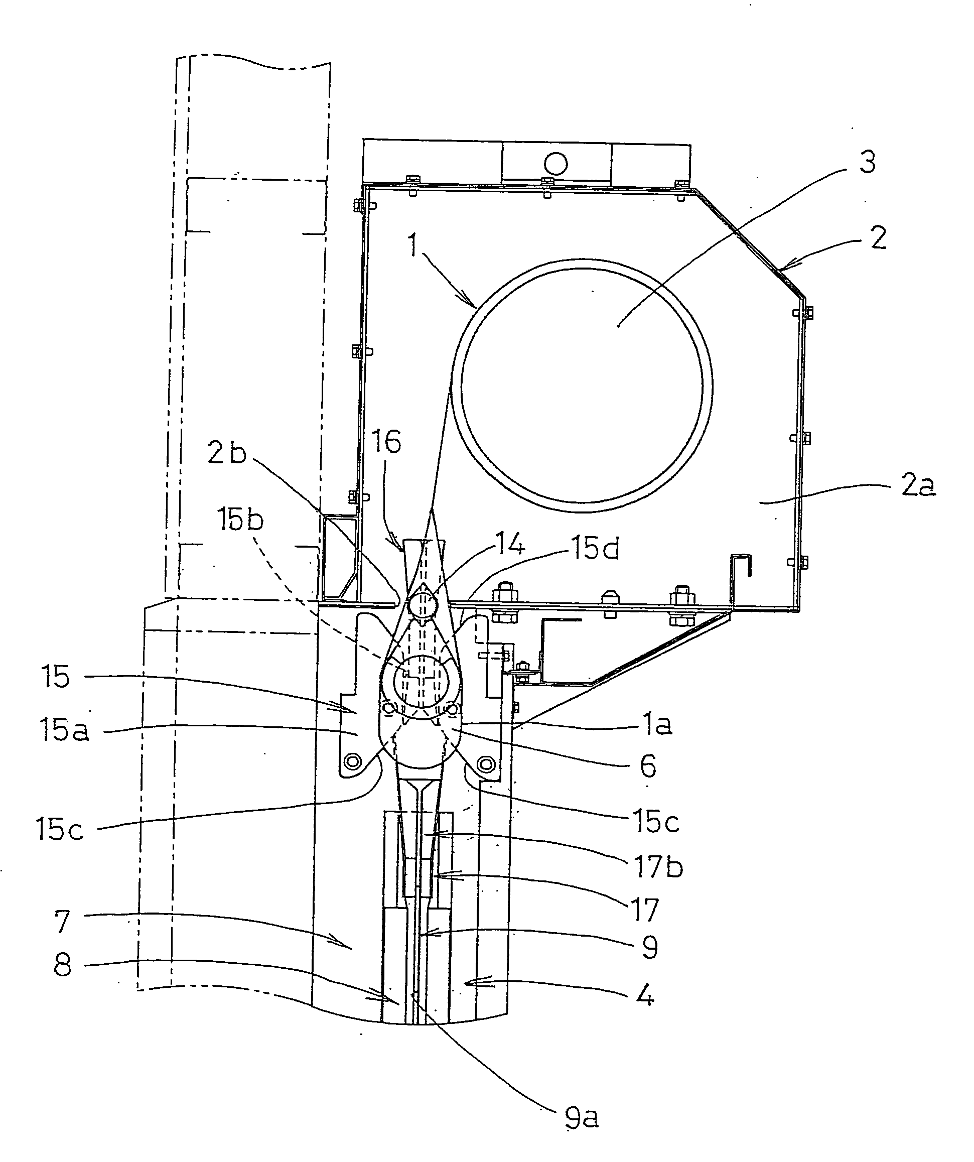
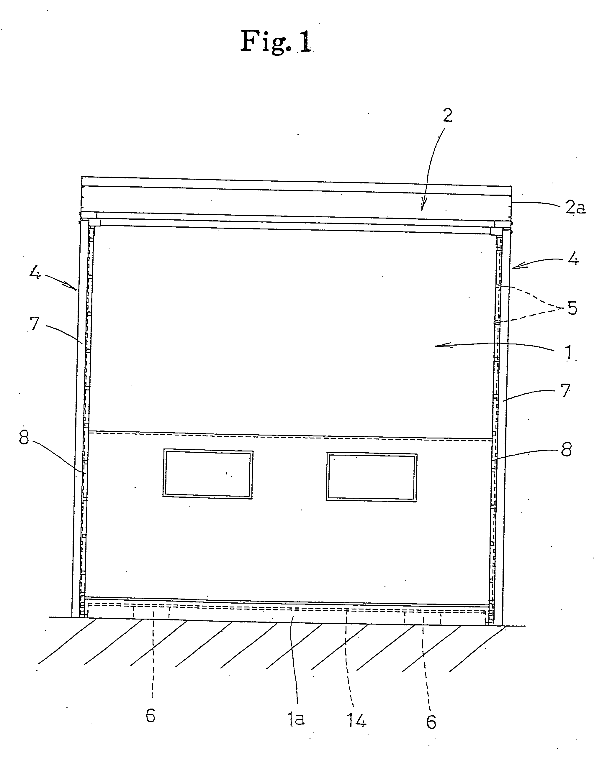
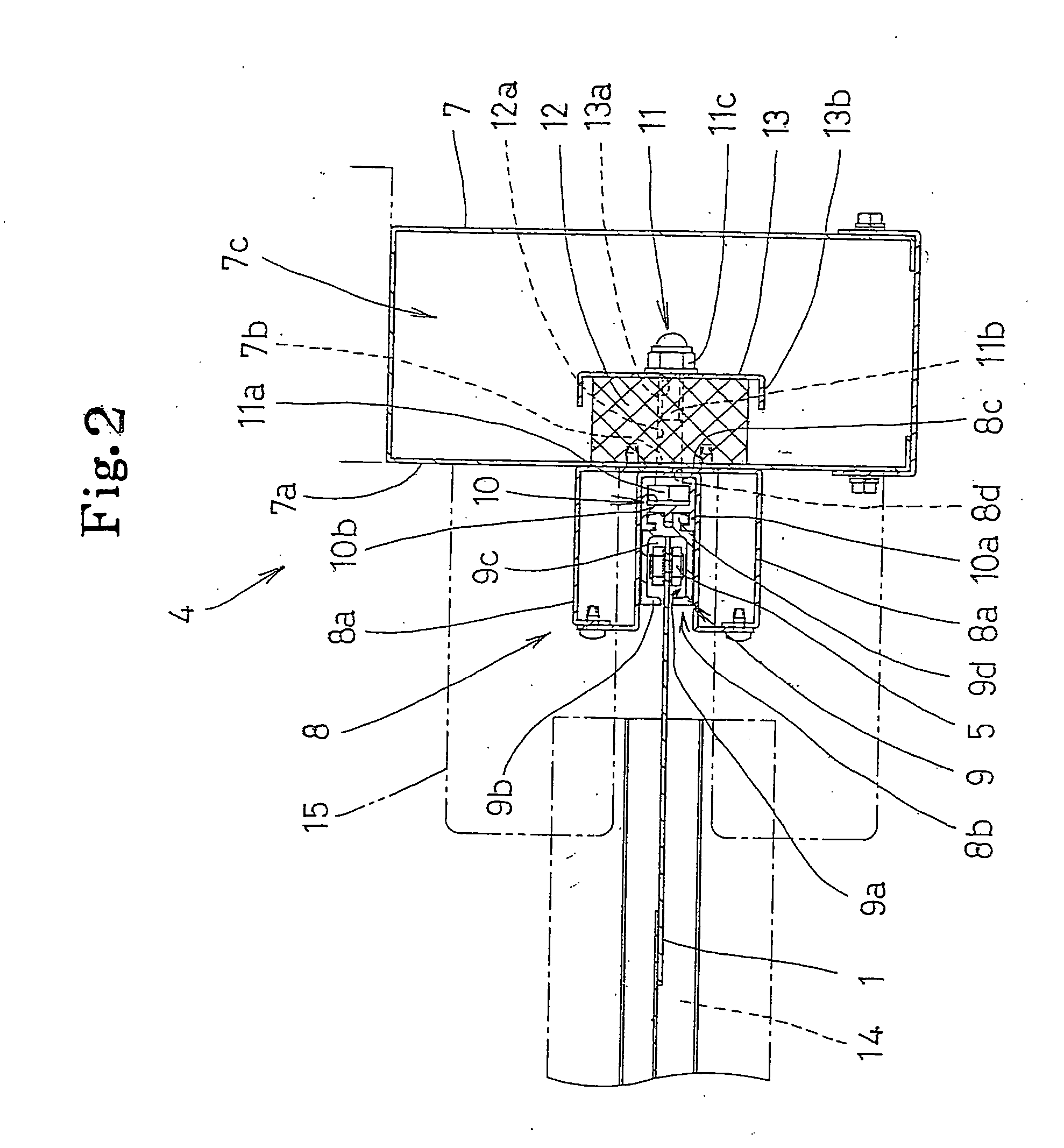
[0050] In the figures, 1 denotes a shutter curtain of the sheet shutter device for opening / closing the opening portion of an architectural structure. The shutter curtain 1 is formed of a flexible sheet material, and wound around the outer periphery (outside) of a winding drum (take-up drum) 3 which is rotatably supported via a shaft on the right and left side plates 2a of a shutter case 2 disposed at a ceiling portion of a structure frame (at the curtain opening side of the structure frame). The shutter curtain 1 is wound off from or taken up to the winding drum 3 in connection with forward / reverse rotation of the winding drum 3 based on an opening / closing operation of an opening / closing unit (not shown), thereby opening / closing the opening portion. At this time, both right and left side edge portions of the shutter curtain 1 are vertically moved while guided by a pair of guide r...


PUM


Abstract

When a fitting piece slipping out of a rail groove of a guide rail in connection with an excessive load on a shutter curtain is restored to the rail groove, the restoration is set to be reliably and noiselessly carried out. An posture holding bar 14 and fitting pieces 5 which are spaced from both right and left sides of the posture holding bar 14 at a predetermined interval are provided at the lower end portion of the shutter curtain 1, and a first guide body 15 for guiding the posture holding bar 14 to the opposing site to the rail groove 9a in the process of an opening / closing operation of the shutter curtain 1, and a second guide body 16 for guiding the fitting piece 5 at the lower end portion of the shutter curtain 1 to the opposing site to the rail groove 9a in conformity with a timing at which the posture holding bar 14 is positionally regulated to the opposing site to the rail groove 9a by the first guide body 15 are provided at the upper side of the rail groove 9a constituting the guide rail 4.

Description

TECHNICAL FIELD [0001] The present invention belongs to the technical field of a sheet shutter device having a flexible shutter curtain provided at an opening portion of an architectural structure or the like. BACKGROUND ART [0002] There is generally known such a type of sheet shutter device wherein engaging pieces are secured to both side portions of a sheet-shaped shutter curtain so as to be spaced at a predetermined pitch in the opening / closing direction, and the engaging pieces are engagingly fitted in rail grooves of guide rails at both side portions of the opening portion so as not to be detachable from the rail grooves and are made to run within the rail grooves, thereby opening / closing the opening portion. In this type of sheet shutter device, because the shutter curtain is formed of a sheet member having flexibility, the shutter curtain is greatly deformed when a large wind blast or a load from an obstruction is applied thereto, so that the guide rail or shutter curtain may...

Claims


Application Information

Patent Timeline
IPC IPC(8): E06B9/17E06B9/13E06B9/58
CPCE06B9/13E06B9/581E06B2009/585
Inventor NAGARE, TOYOHIDETANEMURA, HIDEKIMATSUMURA, ATSUSHIGOTO, MASAHITONAGATA, TAKASHISAKAMOTO, KATSUHIRO
Owner SANWA HLDG CORP
Why Eureka
Try Eureka