Image display device

a display device and image technology, applied in the field of three-dimensional image display systems, can solve the problems of displacement or damage of the plate or the like, and the difficulty of forming the linear polarizing filter line, and achieve the effects of improving workability, good assembleability of the micro-patterned retarder, and difficult workability

Inactive Publication Date: 2006-07-06
SOPHIA CO LTD +1
View PDF3 Cites 17 Cited by
  • Summary
  • Abstract
  • Description
  • Claims
  • Application Information

AI Technical Summary

Benefits of technology

[0013] According to the first aspect of the invention, the invention includes the liquid crystal display panel unit including the liquid crystal display panel with the polarizing plate e disposed at least on the back surface thereof and the micro-patterned retarder to be mounted to the rear surface of the polarizing plate on the back surface of the liquid crystal display panel, the mounting base member including the upright wall having a predetermined height formed with the opening section along the inner periphery of the frame, the storage formed on the front surface side of the upright wall for storing the liquid crystal display panel unit and the diffuser panel and the mounting portion for the Fresnel lens formed on the back surface side thereof, the cover member including the opening corresponding to the opening section, the abutting portion which abuts against the diffuser panel, the abutting portion formed on the outer peripheral area of the opening at a position opposing to the upright wall in a state in which the liquid crystal display panel unit and the diffuser panel are stored in the storage on the front surface side of the upright wall of the mounting base member and then mounted to the mounting base member, whereby the liquid crystal display panel unit and the diffuser panel can be supported in a depressed state in the fore-and-aft direction at the area including the polarizing plate of the liquid crystal display panel by the upright wall of the mounting base member and the abutting portion of the cover member. Therefore, the liquid crystal display panel unit in which the micro-patterned retarder is mounted to the rear surface of the polarizing plate is adequately stored and supported, so that displacement or damage of the micro-patterned retarder due to the supporting state can be prevented.
[0014] Also, the liquid crystal display panel unit is formed with the contact area in which the micro-patterned retarder comes into contact with the polarizing plate which is disposed on the back surface of the liquid crystal display panel and the non-contact areas which do not come into contact with the polarizing plate and oppose the liquid crystal display panel at the end portions with the intermediary of the contact area, and the liquid crystal display panel and the micro-patterned retarder are fixedly bonded to each other at the predetermined portions in the non-contact areas. Therefore, with the supporting structure using the upright wall of the mounting base member and the abutting portion of the cover member in the depressing state, a phenomenon such that the micro-patterned retarder is detached, which occurs in the case where predetermined portions of the non-contact area are simply fixed, can be prevented, whereby the liquid crystal display panel and the micro-patterned retarder are sufficiently supported, and good assembleability of the micro-patterned retarder is achieved.
[0015] For example, in the case of fixedly adhering the adhering area (for example, the entire surface of the contact area), transmission of light through the display surface may be distorted according to the adhering state, and / or the workability is difficult. However, since the adhering portions are predetermined positions in the non-contact area, the workability is improved, and the light must not be transmitted through the adhesive agent on the image display surface, whereby piece-to-piece variations of display of the three-dimensional images among the image display systems are prevented.
[0016] According to the second aspect of the invention, the light source for three-dimensional image display can be arranged adequately and the depth of the system can be reduced to achieve a compact design, whereby the installability can be improved.
[0017] According to the third and fourth aspects of the invention, the liquid crystal display panel unit is stored in the storage of the mounting base member in a state in which the lower surface of the liquid crystal display panel is placed on the upper surface of the bottom plate of the storage, and in this state, the image display surface of the liquid crystal display panel is placed at the position corresponding to the opening section formed on the mounting base member, and the polarizing plate and the micro-patterned retarder are mounted correspondingly. Therefore, constantly stable storage is achieved and hence displacement between the opening section and the position where the image is displayed is eliminated, whereby the three-dimensional images can be provided adequately.

Problems solved by technology

However, it is difficult to form the linear polarizing filter line parts in which the polarization axes are orthogonal with each other at every one horizontal line of the liquid crystal panel as in the related art.
Also, in this case, since the plate or the like is mounted to the liquid crystal panel with the intermediary of the polarizing filter, if they are not supported adequately, displacement or damage of the plate or the like may be resulted.

Method used


Image

  • Image display device
  • Image display device
  • Image display device

Examples


Embodiment Construction

[0035] Referring now to the drawings, an embodiment of the present invention will be described.

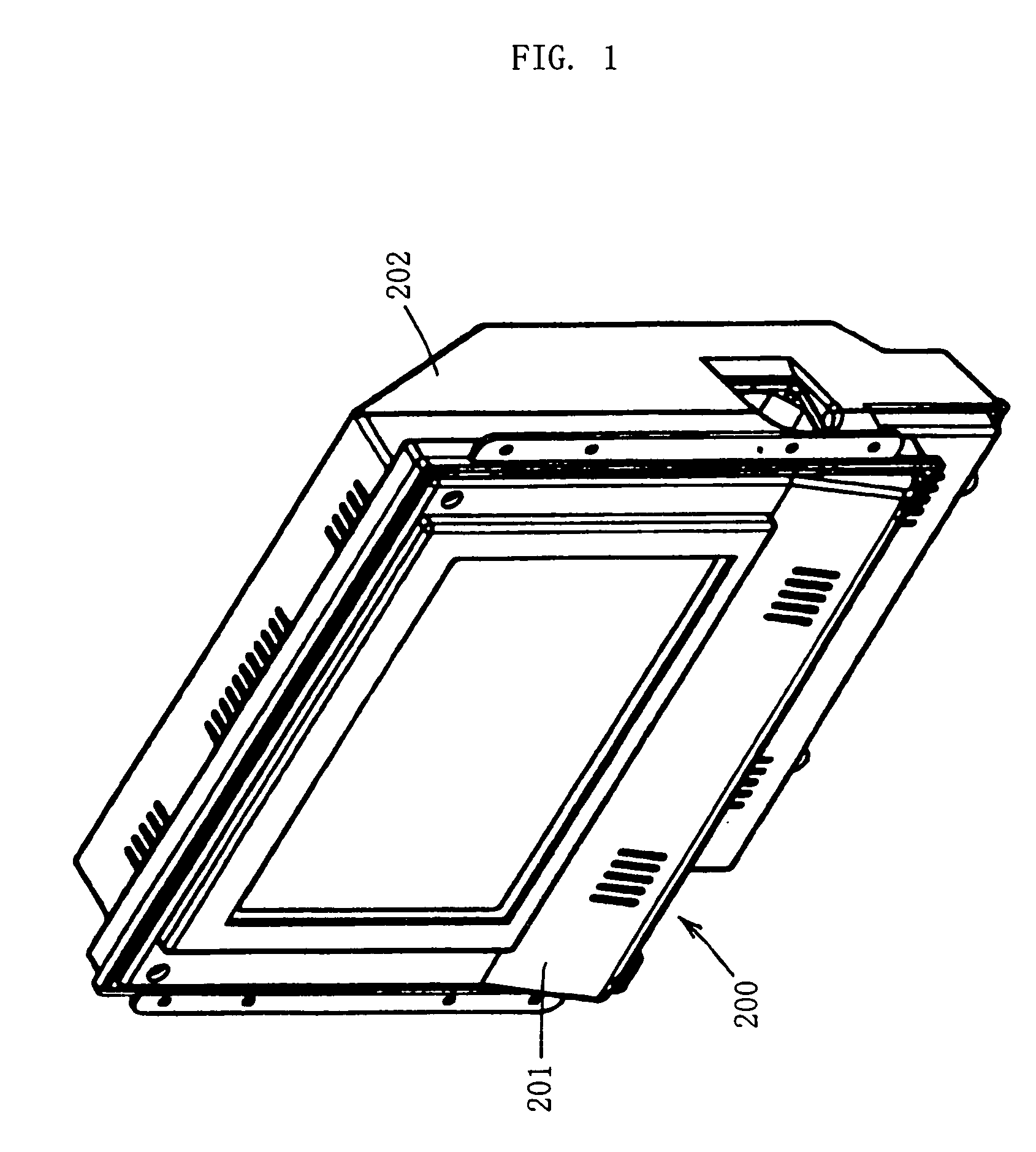
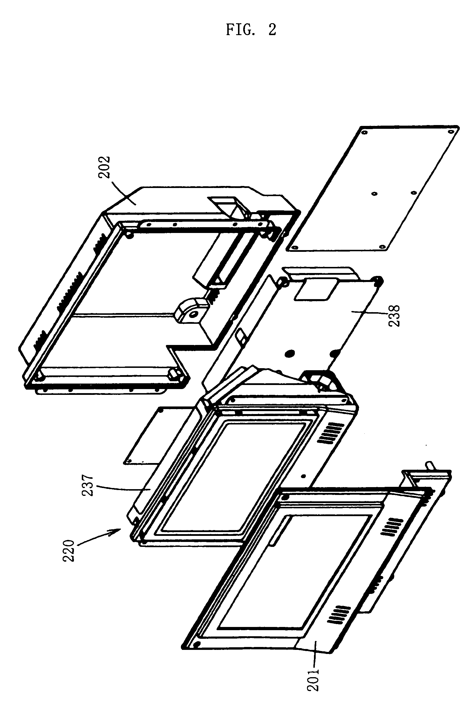
[0036]FIG. 1 and FIG. 2 are a perspective view and an exploded perspective view of an image display box in which an image display system of an embodiment of the present invention is assembled to an exterior case, and FIG. 3 and FIG. 4 are a perspective view of the image display system according to an exemplary embodiment of the present invention and an exploded perspective view of the rear structure thereof.

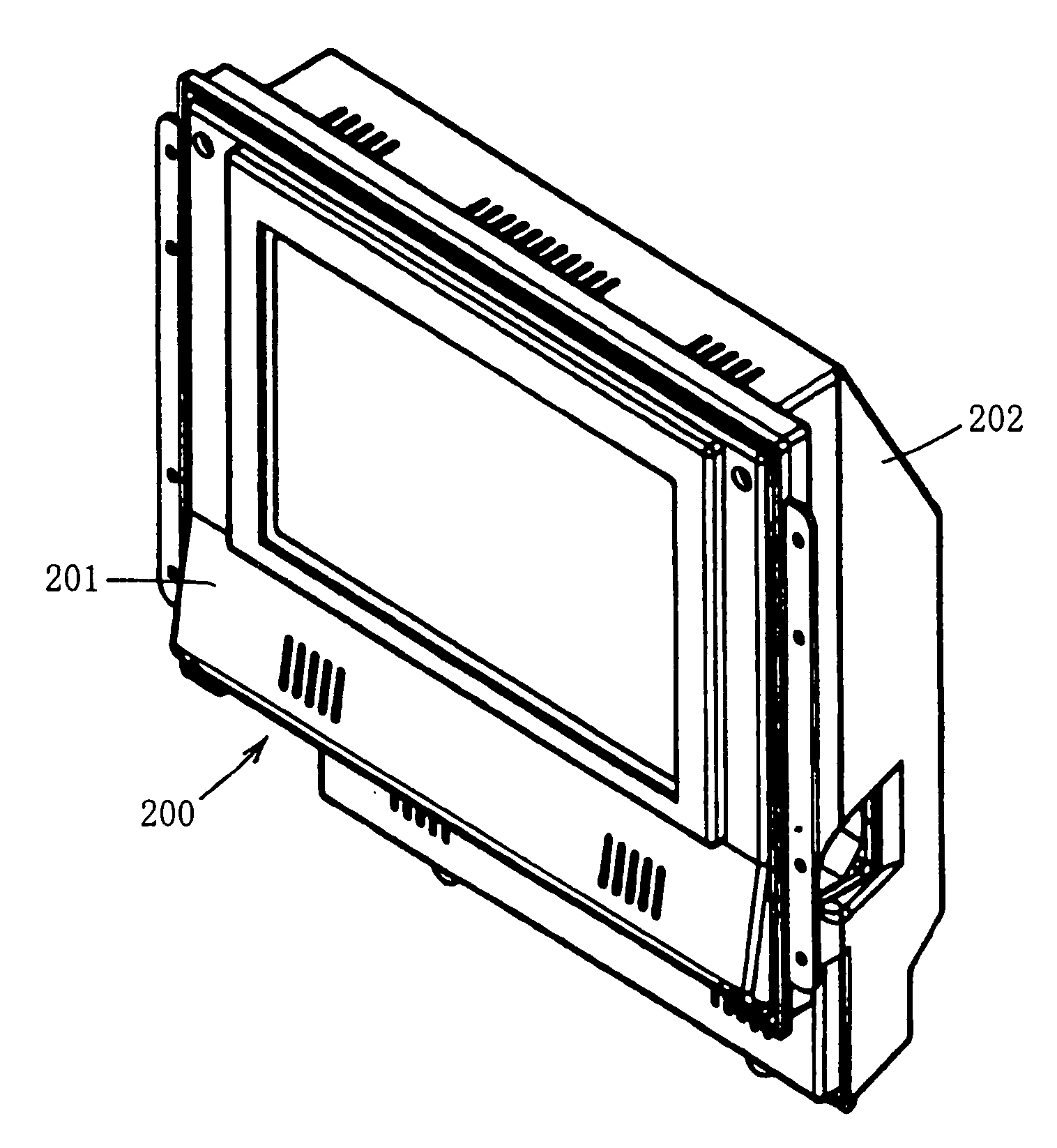
[0037] The exterior case of an image display box 200 includes a front cover panel 201 and a rear cover box 202.

[0038] An image display system 220 includes a front unit 221 (front structure), a rear unit 222 (rear structure), and so on.

[0039] The front unit 221 includes a diffuser (diffuser panel) 226, a liquid crystal display panel unit 227, a Fresnel lens 228 are mounted to a mounting base 223 via a cover frame 224 and a lens holding frame 225, as will be described later.

[0040] Th...


PUM

PropertyMeasurementUnit
sizeaaaaaaaaaa
heightaaaaaaaaaa
areaaaaaaaaaaa

Abstract

The present invention is intended to improve assembleability of a portion of a liquid crystal display panel. In an image display system for displaying images by allowing a light irradiated from behind to be transmitted therethrough, a liquid crystal display panel unit (227) includes a liquid crystal display panel (252) having a polarizing plate (251) at least on the back surface thereof and a micro-patterned retarder (253) mounted to the rear surface of the polarizing plate (251) on the back surface of the liquid crystal display panel (252), and the liquid crystal display panel unit (227) and a diffuser panel (226) to be disposed in front thereof can be supported in the depressed state in the fore-and-aft direction by an upright wall (262) of a mounting base member (223) defining an opening section (260) in an area including the polarizing plates (250, 251) of the liquid crystal display panel (252).

Description

TECHNICAL FIELD [0001] The present invention relates to an image display system and, more specifically, to a three-dimensional image display system in which a viewer can view a three-dimensional image without wearing specific eye-glasses. RELATED ART [0002] Hitherto, a three-dimensional image display system has a configuration such that a polarizing filter part for the right eye and a polarizing filter part for the left eye having the polarization directions intersecting orthogonally with each other are arranged on the left and right of the front surface of a light source, the respective light rays respective polarizing filter parts are made into parallel beams by a Fresnel lens, and irradiated on a liquid crystal display device, each linear polarizing filter line of the polarizing filters on either side of the liquid crystal display device having a polarization direction orthogonal to both polarization directions of an adjacent filter line, and corresponding polarizing filter line ...

Claims


Application Information

Patent Timeline
Patent Type & Authority Applications(United States)
IPC IPC(8): H04N5/66H04N9/12G02F1/1333G02B27/22G02F1/13G02F1/1335G02F1/13357G02F1/13363
CPCG02B27/2214G02B27/26G02F1/133308G02F1/133526G02F2001/133638H04N13/0402G02B30/25G02F1/133638H04N13/302G02B30/27
Inventor IOKI, SADAOARISAWA, SANJITOMITA, SEIJIRO
Owner SOPHIA CO LTD
Why Eureka
Try Eureka