
Injector mounting structure of V-type internal combustion engine

a technology of injector and mounting structure, which is applied in the direction of combustion-air/fuel-air treatment, fuel injection apparatus, charge feed system, etc., can solve the problems of assembleability and a lot of trouble in assembly work, and achieve the effect of superior assembleability

Inactive Publication Date: 2010-08-03
HONDA MOTOR CO LTD
View PDF14 Cites 4 Cited by
  • Summary
  • Abstract
  • Description
  • Claims
  • Application Information

AI Technical Summary

Benefits of technology

[0013]Therefore, by providing the pair of the injectors so as to project from the single fuel supply pipe, the pair of injectors may be mounted simultaneously to the respective mounting holes of the air-intake pipes. Thus, the number of components is small, the assembly work is easy, and the superior assembleability is achieved.
[0014]According to an embodiment of the present invention, since the water drain holes are formed on the mounting holes formed on the air-intake pipes on the respective sides, even when the mounting holes of the air-intake pipes to which the injectors are fitted from above are formed to have a length sufficient for firmly holding the distal end portions of the injector, water drops or the like may be drained through the water drain holes so that accumulation may be avoided.

Problems solved by technology

Therefore, the assembly work takes a lot of trouble and the assembleability has a problem to solve.

Method used


Image

  • Injector mounting structure of V-type internal combustion engine
  • Injector mounting structure of V-type internal combustion engine
  • Injector mounting structure of V-type internal combustion engine

Examples


Embodiment Construction

[0026]Referring now to FIG. 1 to FIG. 9, an embodiment of the present invention will be described.

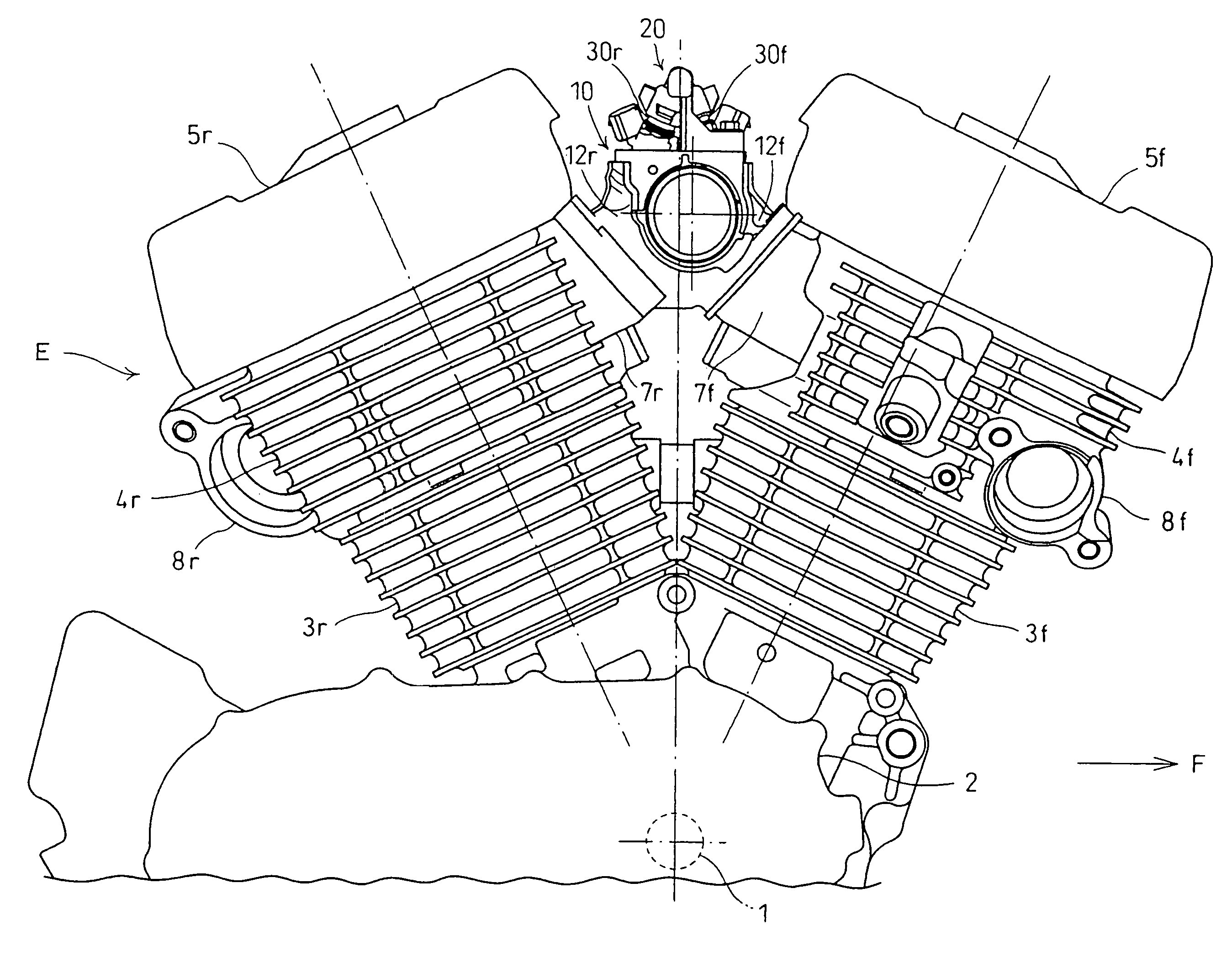
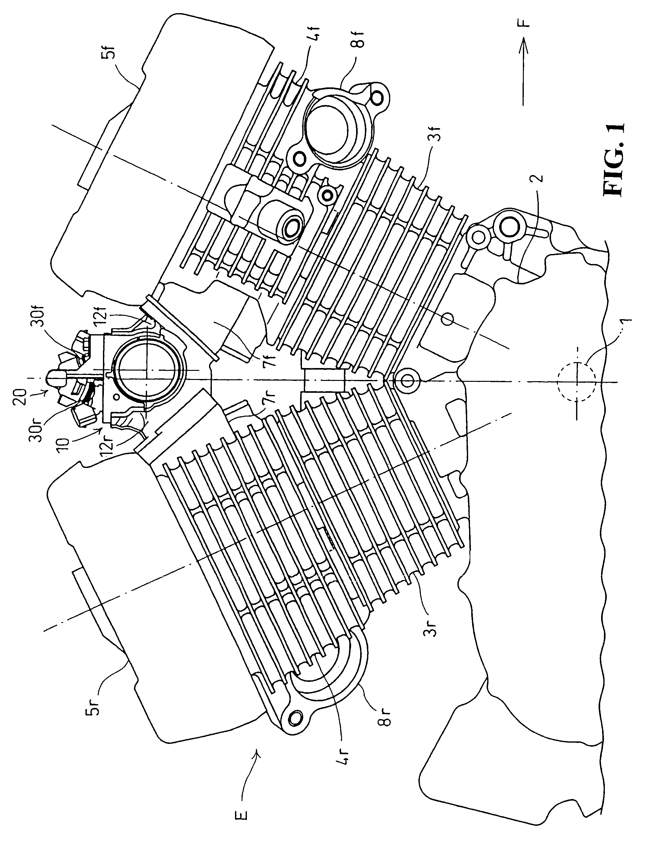
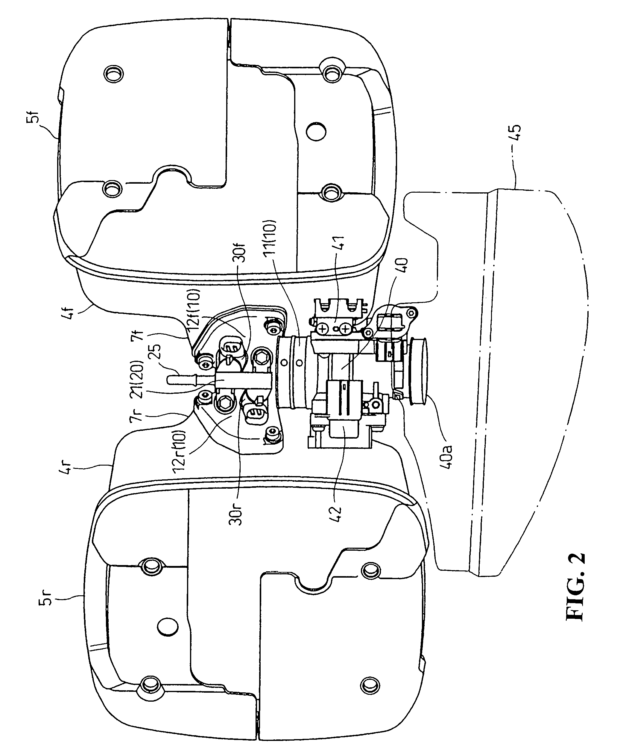
[0027]A V-type internal combustion engine E according to this embodiment is a two-cylinder water-cooled four-stroke internal combustion engine formed into a V-shape in the fore-and-aft direction, which is mounted transversely to a motorcycle with a crankshaft 1 oriented horizontally in the lateral direction. A top view of the V-type internal combustion engine E is shown in FIG. 1, and a right side view thereof is shown in FIG. 2.

[0028]In this embodiment, the front, rear, left, and right are defined based on the direction of travel of a vehicle.

[0029]The V-type internal combustion engine E includes a front bank cylinder 3f and a rear bank cylinder 3r extended obliquely upwardly from a crankcase 2, cylinder heads 4f, 4r placed on the front bank cylinder 3f and the rear bank cylinder 3r inclined in the fore-and-aft direction with cylinder head covers 5f, 5r covered respectively thereon.

[00...


PUM


Abstract

An injector mounting structure for a V-type internal combustion engine includes an intake manifold arranged in a V-bank. A fuel supply pipe extends linearly in parallel to a crankshaft and is disposed in the V-bank. A pair of injectors are branched in an inverted V-shape in side view from the direction of the axial line of the fuel supply pipe from two branch portions P, Q apart from each other in the direction of the axial line of the fuel supply pipe and extend in parallel to each other and obliquely at an acute angle α with respect to a segment PQ connecting the two branch portions P, Q in top view. The injectors are mounted by fitting distal end portions of the pair of injectors respectively into mounting holes formed on air-intake pipes of the intake manifold on the respective sides.

Description

CROSS-REFERENCE TO RELATED APPLICATIONS[0001]The present application claims priority under 35 USC 119 to Japanese Patent Application No. 2006-335855 filed on Dec. 13, 2006 the entire contents thereof is hereby incorporated by reference.BACKGROUND OF THE INVENTION[0002]1. Field of the Invention[0003]The present invention relates to an injector mounting structure with respect to an air-intake device in a V-type internal combustion engine.[0004]2. Description of Background Art[0005]In the related art, for example, in a V-type internal combustion engine, with the arrangement of an air intake device for sucking air in respective cylinders at a V-bank between the cylinders, an intake manifold having a structure for branching a common air-intake passage to the respective cylinders as a branched air-intake passage is achieved, so that the air-intake device may be downsized and hence the bank angle may be reduced. See, for example, Japanese Patent No. 3106724 (FIG. 1).[0006]In the V-type int...

Claims


Application Information

Patent Timeline
Patent Type & Authority Patents(United States)
IPC IPC(8): F02M61/14F02M61/18
CPCF02M35/10085F02M35/10216F02M69/465F02M69/042F02M35/116
Inventor CHO, MASAKIARIGA, YOSUKE
Owner HONDA MOTOR CO LTD
Learn More