Optical beam transformation system and illumination system comprising an optical beam transformation system

an optical beam and transformation system technology, applied in the field of optical beam transformation systems, can solve the problems of reducing the polarization-varying effect of conventional beam transformation systems, such as axicon systems, and further losses at downstream deflecting mirrors or polarization-dependent beam splitter layers, so as to reduce the polarization-varying

Active Publication Date: 2006-07-06
CARL ZEISS SMT GMBH
View PDF24 Cites 147 Cited by
  • Summary
  • Abstract
  • Description
  • Claims
  • Application Information

AI Technical Summary

Benefits of technology

The invention provides an optical beam transformation system that reduces polarization-varying effects compared to conventional systems.

Problems solved by technology

The technical problem addressed in this patent text is the nonuniform intensity distribution caused by the polarization state of the light source in a microlithography projection exposure apparatus. The nonuniform intensity distribution results in the case of an axicon system with conical axicon surfaces and a single-beam transformation system. The text describes various methods for optimizing the illumination distribution in the exit pup of the axicon system by adjusting the position of the axicon surfaces or the inclination angle of the axicon surfaces. The text also discusses the use of a polarizer with conical surfaces to produce tangential or radial polarization. The problem is to maintain polarization in the case of conventional beam transformation systems.

Method used


Image

  • Optical beam transformation system and illumination system comprising an optical beam transformation system
  • Optical beam transformation system and illumination system comprising an optical beam transformation system
  • Optical beam transformation system and illumination system comprising an optical beam transformation system

Examples


first embodiment

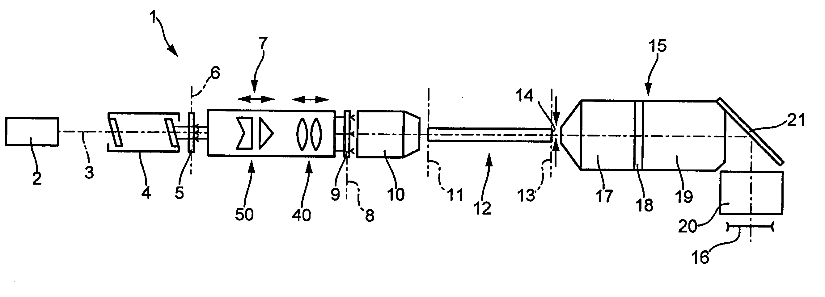
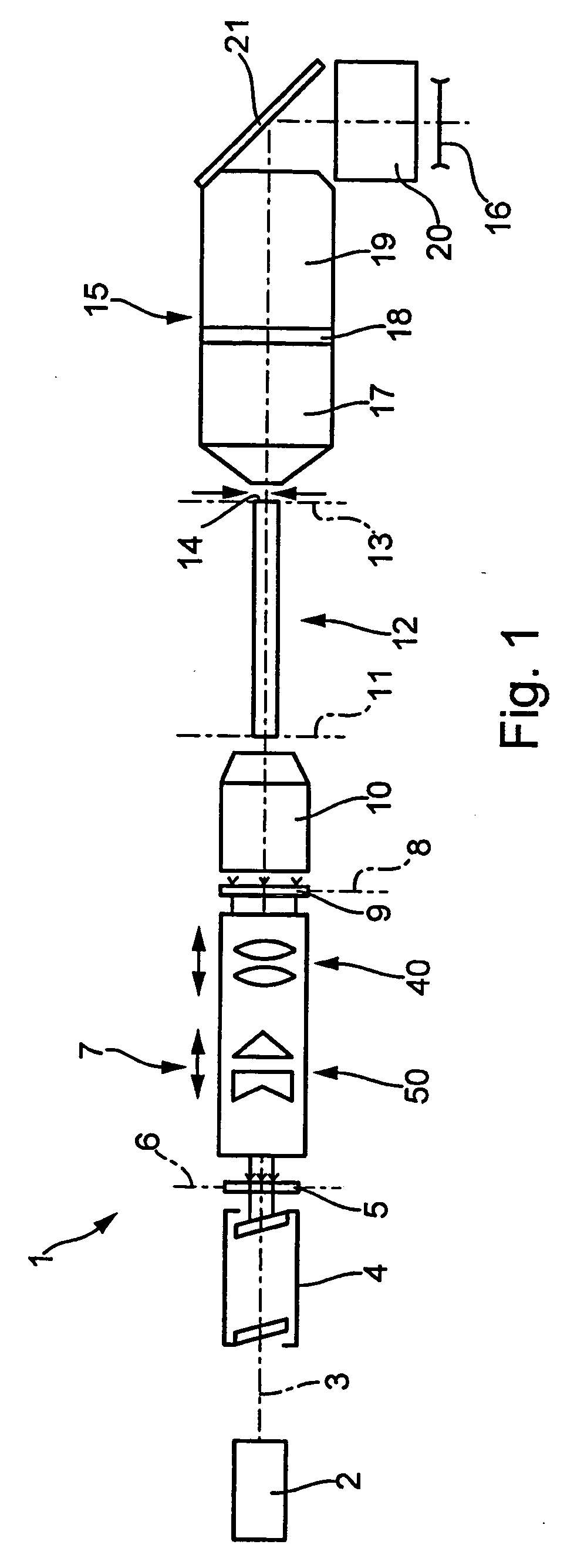
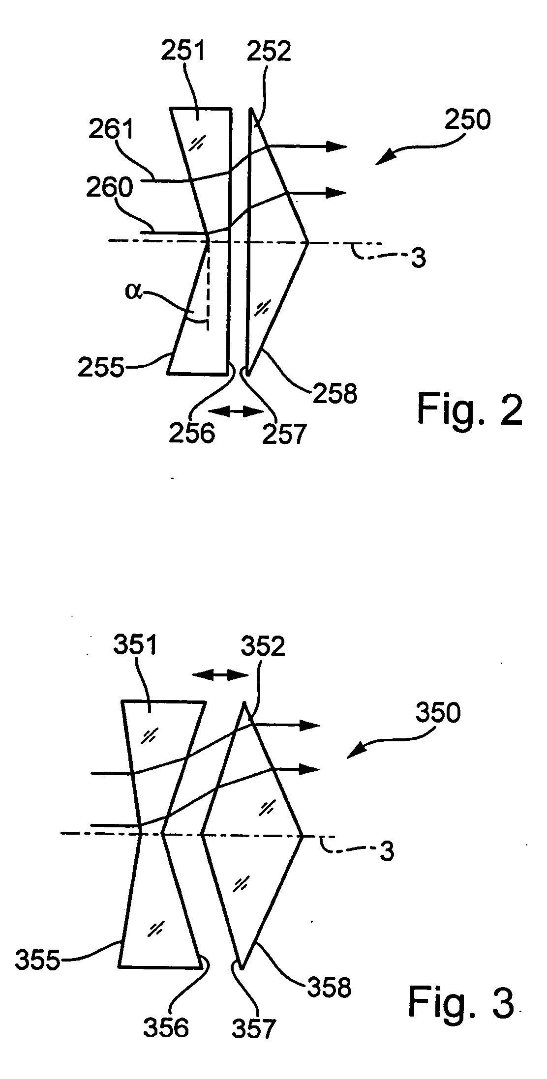
[0123]FIG. 2 shows a substantially polarization-maintaining axicon system 250. It comprises a first axicon element 251 and a second axicon element 252, which is arranged downstream thereof in the direction in which the light runs and whose axial spacing can be infinitely adjusted by means of an adjusting device (not shown) and, if appropriate, can be reduced to a spacing of zero. The first axicon element 251 has a concave conical entrance surface 255 which forms the entrance surface and first axicon surface of the axicon system, as well as a substantially planar exit surface 256. The inclination angle α of the axicon surface, which is measured between a plane perpendicular to the optical axis and a tangent plane at the cone, is approximately 20° to 25°. The second axicon element 252 has a substantially planar entrance surface 257 and a convex conical exit surface 258 which forms the exit surface of the axicon system and at the same time its second axicon surface. The inclination ang...

third embodiment

[0128] In an axicon system 450 in FIG. 4, corresponding reference numerals are increased again by 100. Here, the first axicon element 451 has a concave conical entrance surface 455 and a convex spherical (or slightly aspheric, if appropriate) exit surface 456, while the subsequent second axicon element 452 has a concave spherical (or slightly aspheric, if appropriate) entrance surface 357 corresponding to the surface 456, and a conical exit surface 458. Because of the spherically curved intermediate surfaces 456, 457, whose spacing can be adjusted, the deflecting action, which leads to a radial redistribution of light intensity, further has superimposed on it a focusing action of the axicon system such that the radiation emerging from the exit surface 458 of the axicon system runs convergently. An axicon system with an overall “positive refractive power” is thus created. Here, again, the beam deflection is advantageously distributed over all four optical surfaces of the axicon syste...

fifth embodiment

[0130]FIG. 6 shows an axial top view of an axicon surface 655 of an axicon system 650 of a The axicon element comprises a plurality of separate individual elements which are arranged circularly about the optical axis and in each case have the form of wedges. Such a wedge element of triangular shape is marked by bold lines. The individual elements arranged in the shape of a rosette can be fixed on one another and thus form with an axicon surface a pyramid element which has a polygonal pyramid shape which is assembled from a plurality of planar pyramid facets 670 which border one another or are arranged at a slight spacing from one another. It is thereby possible to create a multiple prism with a number of prism elements which are arranged in a circular arrangement such that light which comes from a point light source arranged on the optical axis runs through the prism elements and after the passage a number of component beams which corresponds to the number of prism elements is pres...


PUM


Abstract

An optical beam transformation system, which can be designed to be utilized in an illuminating system of a microlithograpic projection exposure apparatus, has a sequence of optical elements arranged along an optical axis of the optical beam transformation system and designed for transforming an entrance light distribution striking an entrance surface of the optical beam transformation system into an exit light distribution emerging from an exit surface of the optical beam transformation system by radial redistribution of light intensity. The optical elements include at least one transformation element causing a radial redistribution of light intensity and having at least one transformation surface inclined to the optical axis and causing a polarization-selective reflection of a light distribution incident on the transformation surface according to an efficiency symmetry characteristic for the transformation surface. The optical elements further include at least one optical compensation element effecting a spatially dependent compensation of transmission inhomogeneties caused by the polarization-selective reflection at the transformation surface according to a compensation symmetry adapted to the efficiency symmetry of the transformation surface. Axicon elements with axicon surfaces may be used as transformation elements.

Description


Claims


Application Information

Patent Timeline
Owner CARL ZEISS SMT GMBH
Why Eureka
Try Eureka