Securing time for identifying cause of asynchronism in fault-tolerant computer

a fault-tolerant computer and time-securization technology, applied in the field of fault-tolerant computers, can solve the problems of inability to ensure the operation of fault-tolerant computers, the non-conformity of data stored in the main storage units of cpu subsystems, and the inability to shorten the resynchronization process that is to be performed subsequently

Inactive Publication Date: 2006-07-06
NEC CORP
View PDF52 Cites 15 Cited by
  • Summary
  • Abstract
  • Description
  • Claims
  • Application Information

AI Technical Summary

Benefits of technology

[0016] It is an object of the present invention to provide a fault-tolerant computer which is capable of identifying the cause of an asynchronous operation which is detected, prior to the start of a resynchronizing process, and a method of controlling a fault-tolerant computer.
[0017] Another object of the present invention is to provide a fault-tolerant computer which is capable of minimizing the nonconformity of data stored in main storage units of CPU subsystems of the fault-tolerant computer, which nonconformity is caused by identifying the cause of an asynchronous operation prior to the start of a resynchronizing process, and a method of controlling a fault-tolerant computer.
[0023] With the above arrangement, when an asynchronous operation is detected, it is possible to secure a period of time required to identify the cause of the asynchronous operation on a software or hardware basis before the DMA transfer process as a resynchronizing process is started.
[0027] With the above arrangement, the predetermined time to be reached in the DMA controller is a time when the interrupt signal is sent from the DMA controller or the access comparator to the CPU. The interrupt signal may substitute for a signal for indicating to the CPU that the data stored in the main storage unit after the time when the interrupt signal is sent cannot be transferred by the DMA controller according to the DMA transfer process. As the period of time required to identify the cause of an asynchronous operation may be limited to a minimum period of time required to perform the DMA transfer process, the period of time required to identify the cause of the asynchronous operation can be secured, and the nonconformity of the data stored in the main storage units, which is caused by securing the period of time required to identify the cause of the asynchronous operation, may be held to a minimum, thereby shortening the resynchronizing process.
[0029] With the above arrangement, the CPU bus controllers may directly compare operations of the CPU buses with each other to detect an asynchronous operation early before the nonconformity of data stored in the main storage units grows, thereby shortening the resynchronizing process.

Problems solved by technology

Causes of the asynchronism are of relatively minor nature, including a CPU failure, a software error caused by a radiation to change the data stored in the main storage units, and an operational event that is not guaranteed by the lock-step system.
However, when an asynchronous operation of the fault-tolerant computer disclosed in Document 1 is detected, the cause of the asynchronous operation is not detected, but the resynchronizing process is immediately carried out to copy the updated data of the data stored in the main storage unit of one of the CPU subsystems to the main storage unit of the other CPU subsystem.
Consequently, if the asynchronous operation is caused by a failure of the CPU of the CPU subsystem from which the updated data is to be copied, then the fault-tolerant computer will not be guaranteed for its operation even after the resynchronizing process is fully completed.
If a long period of time is consumed to identify the cause of an asynchronous operation, however, because the CPU subsystems keep operating out of synchronism during that period of time, the nonconformity of the data stored in the main storage units of the CPU subsystems grows, making it difficult to shorten the resynchronizing process that is to be performed subsequently.

Method used


Image

  • Securing time for identifying cause of asynchronism in fault-tolerant computer
  • Securing time for identifying cause of asynchronism in fault-tolerant computer
  • Securing time for identifying cause of asynchronism in fault-tolerant computer

Examples


Embodiment Construction

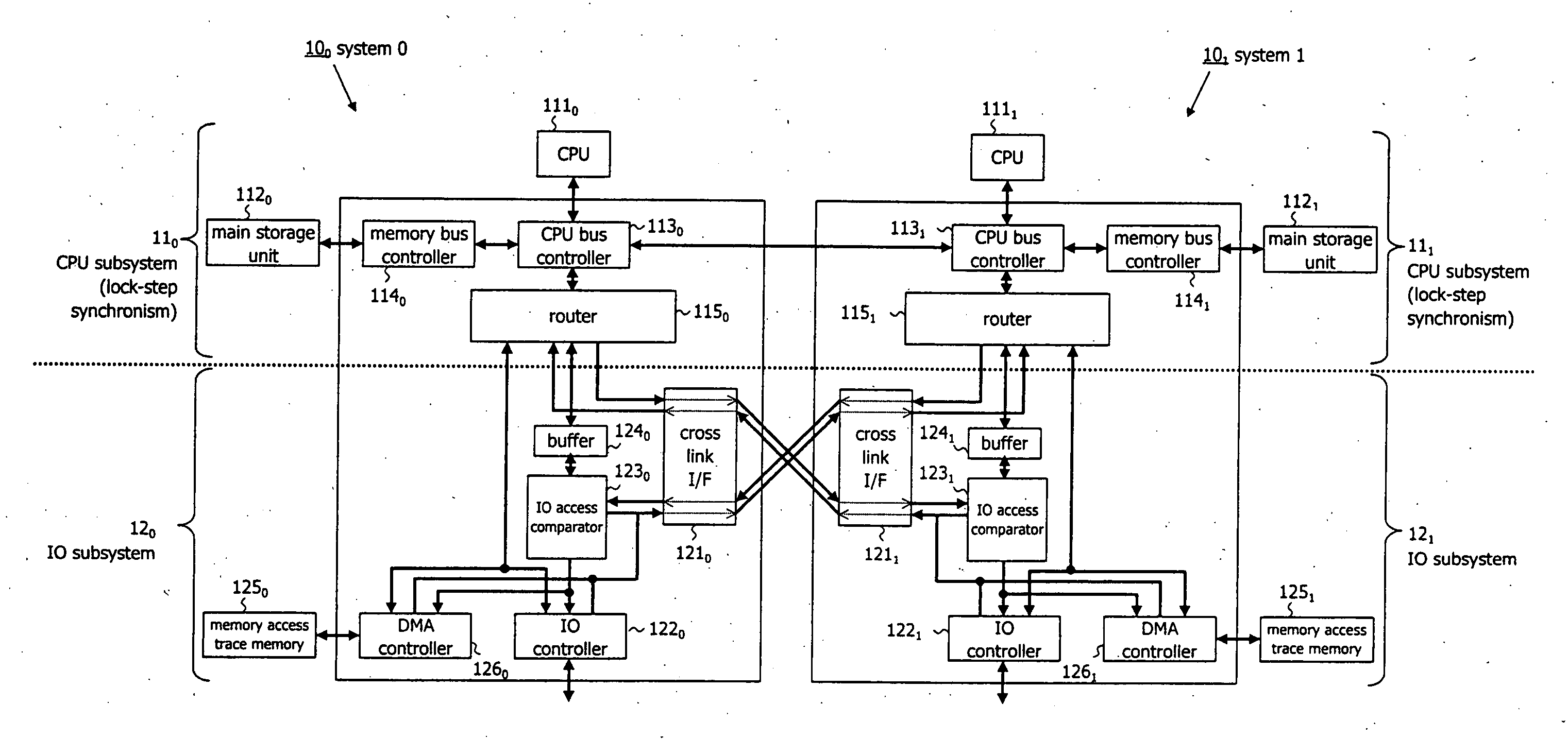
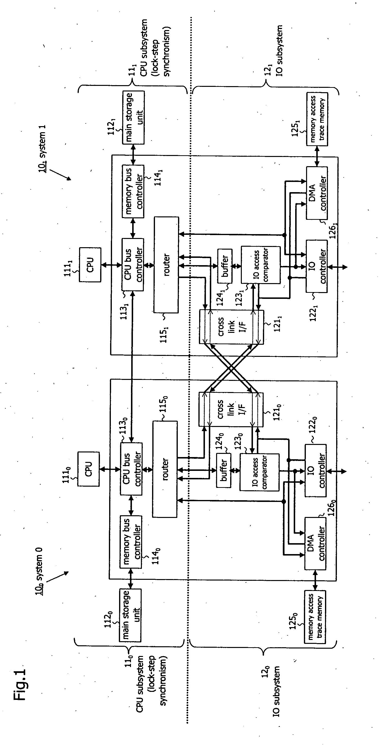
[0040] As shown in FIG. 1, a fault-tolerant computer according to an embodiment of the present invention has a pair of duplex systems, i.e., system 100 (system 0) comprising CPU subsystem 110 and IO subsystem 120 and system 101 (system 1) comprising CPU subsystem 111 and IO subsystem 121. CPU subsystem 110 and CPU subsystem 111 operate synchronously with each other according to lock-step synchronism (hereinafter referred to simply as “synchronism”).

[0041] CPU subsystem 110 comprises CPU 1110, main storage unit 1120, CPU bus controller 1130, memory bus controller 1140, and router 1150. IO subsystem 120 comprises cross link I / F 1210, IO controller 1220, IO access comparator 1230, buffer 1240, memory access trace memory 1250, and DMA (Direct Memory Access) controller 1260.

[0042] Similarly, CPU subsystem 11, comprises CPU 1111, main storage unit 1121, CPU bus controller 1131, memory bus controller 1141, and router 1151. IO subsystem 121 comprises cross link I / F 1211, IO controller 122...


PUM


Abstract

A fault-tolerant computer has a pair of duplex systems having respective CPU subsystems that are operable identically in lock-step synchronism. Each of the duplex systems has a CPU, a main storage unit, a CPU bus controller, and a DMA controller. The CPU and the main storage unit are included in each of the CPU subsystems. The CPU bus controller continuously operates the CPU of its own system even if it detects an asynchronous operation while the CPU subsystems are operating in synchronism with each other. Even if the asynchronous operation is detected, the DMA controller holds a DMA transfer process for transferring data stored in the main storage unit of its own system or the other system to the main storage unit of the other system or its own system after the asynchronous operation is detected until a certain time is reached.

Description

BACKGROUND OF THE INVENTION [0001] 1. Field of the Invention [0002] The present invention relates to a fault-tolerant computer with DMR (Double Modular Redundancy) systems each including a CPU subsystem having a CPU and a main storage unit and an IO subsystem, and a method of controlling such a fault-tolerant computer. [0003] 2. Description of the Related Art [0004] In recent years, growing computer functionality has enabled computers to be used in a wider variety of fields. Such computers are required to operate continuously even in the event of faults. One solution to meet the requirement is fault-tolerant technology with duplex systems. [0005] A fault-tolerant computer built on the fault-tolerant technology has duplex systems each including a CPU subsystem having a CPU and a main storage unit and an IO subsystem. Some fault-tolerant computers employ a lock-step system for operating the two CPU subsystems synchronously with each other based on synchronous clocks. [0006] In fault-t...

Claims


Application Information

Patent Timeline
Patent Type & Authority Applications(United States)
IPC IPC(8): G06F11/00
CPCG06F11/1658
Inventor MIZUTANI, FUMITOSHI
Owner NEC CORP
Why Eureka
Try Eureka