Actuator position control method and corresponding apparatus

a technology of actuator position and control method, which is applied in the direction of disposition/mounting of heads, instruments, data recording, etc., can solve the problems of power consumption and acoustic noise, the time is not visible before the system, and the bits can be detected again

Inactive Publication Date: 2006-07-20
KONINKLIJKE PHILIPS ELECTRONICS NV
View PDF7 Cites 2 Cited by
  • Summary
  • Abstract
  • Description
  • Claims
  • Application Information

AI Technical Summary

Benefits of technology

[0014] The present invention allows to solve the problem mentioned above, since the preliminary detection of the occurring defect before said defect reaches the main spot is used to immediately adapt the normalization and avoids the peaks observed in the error-signals.

Problems solved by technology

In such a situation, the servo has to work hard to get to the correct position again, which results in some noticeable time before the system is in lock again and bits can again be detected.
Additionally, it also results in power consumption and acoustical noise.

Method used


Image

  • Actuator position control method and corresponding apparatus
  • Actuator position control method and corresponding apparatus
  • Actuator position control method and corresponding apparatus

Examples


Embodiment Construction

[0022] An example of embodiment of the invention will now be described below. As said above, when defects occur on optical discs, it is important that the servo system of the disc drive keeps working as good as possible. When a defect has occurred, less laser light is reflected from the disc than in a normal situation and the signal coming from photodetectors (and used as a measure for the reflected laser light) comes below a predefined threshold. A defect detector is then switched on and the servo system is kept stiff until the signal again comes above its threshold level.

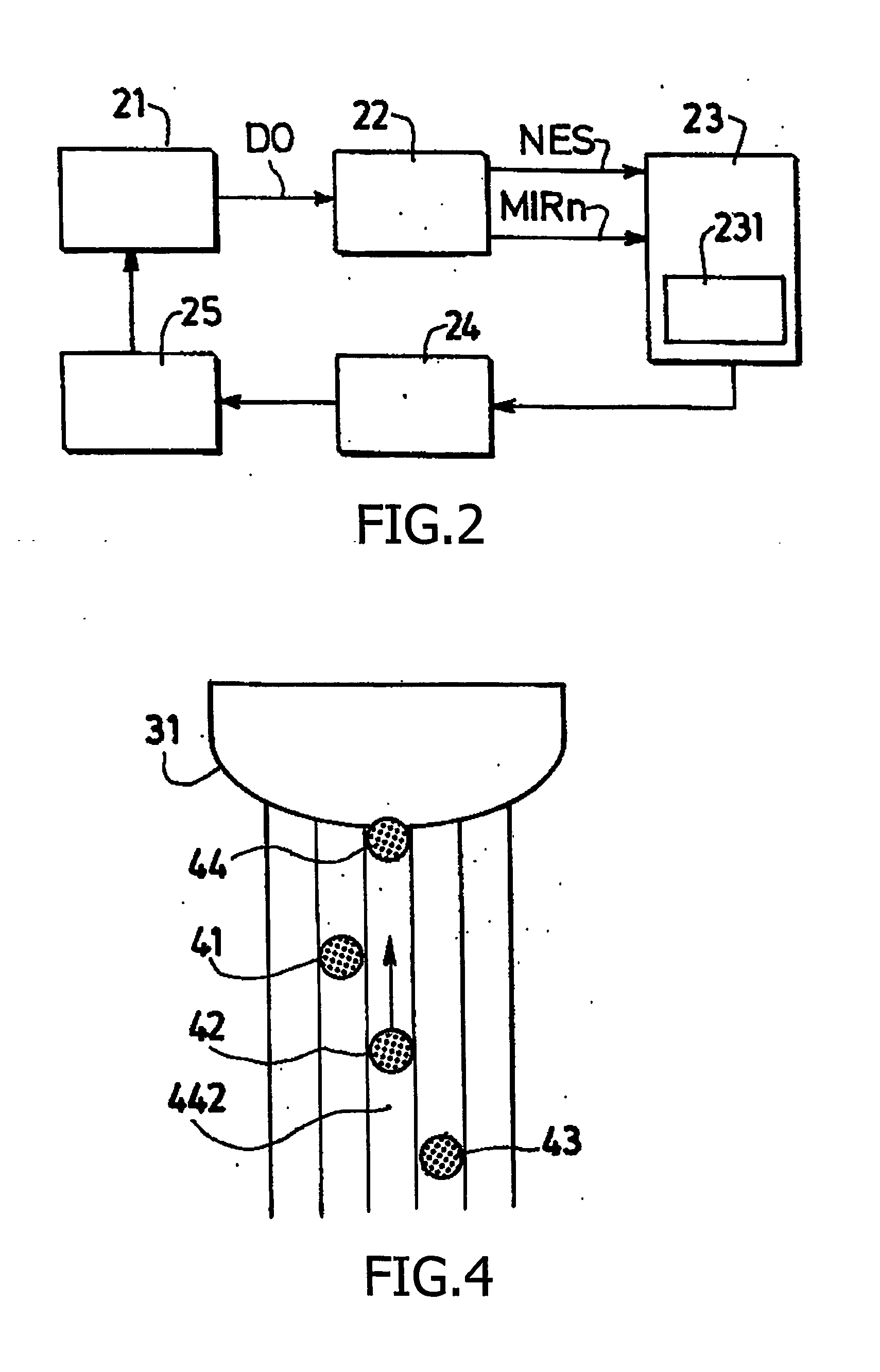
[0023] These operations take place in a servo control system. As illustrated in FIG. 2, the servo system of an optical disc drive schematically comprises an optical system 21, followed by a preprocessing circuit 22 receiving the detector outputs DO from the optical system 21 and sending its outputs to a servo control system 23, including inter alia a defect detector 231. The output of the servo control system 23 ...


PUM

PropertyMeasurementUnit
distanceaaaaaaaaaa
timeaaaaaaaaaa
thresholdaaaaaaaaaa

Abstract

The invention relates to an actuator position control method for use in a recorded information reproducing apparatus. Front, main and rear beams (or at least one main beam) are directed onto a recorded track formed on a rotating optical recording medium and respective first, second and third signals are produced in response to light reflected by said recorded track when it is scanned by the main beam. The control method comprises the steps of producing from a source of light said beam(s); scanning with the main beam the recorded track; controlling the position of said main beam with respect to the recorded track in response to position control signals, and reading the recorded information by means of a specific processing operation of the second signal. According to the invention, said method also comprises the steps of scanning in advance, with an additional beam arranged in such a way that it precedes the main one in the scanning direction, a portion of recorded track which is located in front of the portion of recorded track that will be later, after a predetermined delay, scanned by the main beam; and, on the basis of signals generated in response to the occurrence of possible defects, cancelling the effects of the variations of said corresponding signals, subsequent to variations of reflected light caused by said defects, by means of a modification of the position control signals for controlling the position of said main beam.

Description

FIELD OF THE INVENTION [0001] The present invention relates to an actuator position control method for use in a recorded information reproducing apparatus in which at least one beam is directed onto a recorded track formed on a rotating optical recording medium and a corresponding signal is produced in response to light reflected by said recorded track when scanned by said beam, said method comprising the steps of: [0002] producing from a source of light at least said beam; [0003] scanning with said beam the recorded track; [0004] controlling the position of said beam in response to position control signals. The invention may be applied to all optical disc drives that make use of a rotating optical disc (DVD, Blu-ray disc, Small form Factor Optical disc, . . . ) BACKGROUND OF THE INVENTION [0005] An optical disc player comprises inter alia a servo circuit in which an optical beam, emitted for example by a laser oscillator, is caused to correctly follow a track on a disc, in order t...

Claims


Application Information

Patent Timeline
Patent Type & Authority Applications(United States)
IPC IPC(8): G11B7/00G11B7/09
CPCG11B7/0903G11B7/0941G11B7/0948G11B7/09
Inventor HELWEGEN, IVON FRANCISCUSJANSSEN, ANTHONIUS PETRUS
Owner KONINKLIJKE PHILIPS ELECTRONICS NV
Why Eureka
Try Eureka