Surface water drainage system

Active Publication Date: 2006-07-20
ACO SEVERIN AHLMANN GMBH & CO KG
View PDF16 Cites 19 Cited by
  • Summary
  • Abstract
  • Description
  • Claims
  • Application Information

AI Technical Summary

Benefits of technology

[0009] It is the object of the invention to provide a surface water drainage system of the kind cited at the outset further, in such a way that manufacture and assembly are simplified while still ensuring at least equal durability and reliability of fixation.

Problems solved by technology

The problems generally encountered with such drainage systems, in particular drainage channels, are associated with the fact that on one hand the cover lying on the structure installed in the ground must be fixed in position so firmly that even the impulse-like forces encountered when a vehicle travels over the covers cannot release them.
The structure of the known systems is relatively elaborate and hence costly.

Method used


Image

  • Surface water drainage system
  • Surface water drainage system
  • Surface water drainage system

Examples


Embodiment Construction

[0036] In the following description, the same reference numerals are used for identical parts and parts with identical actions.

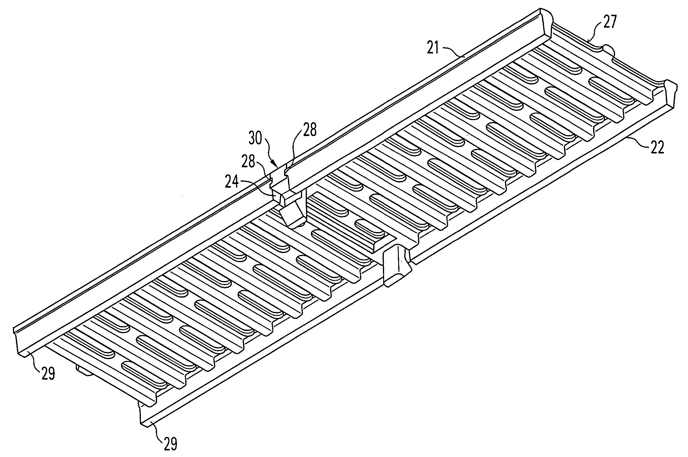
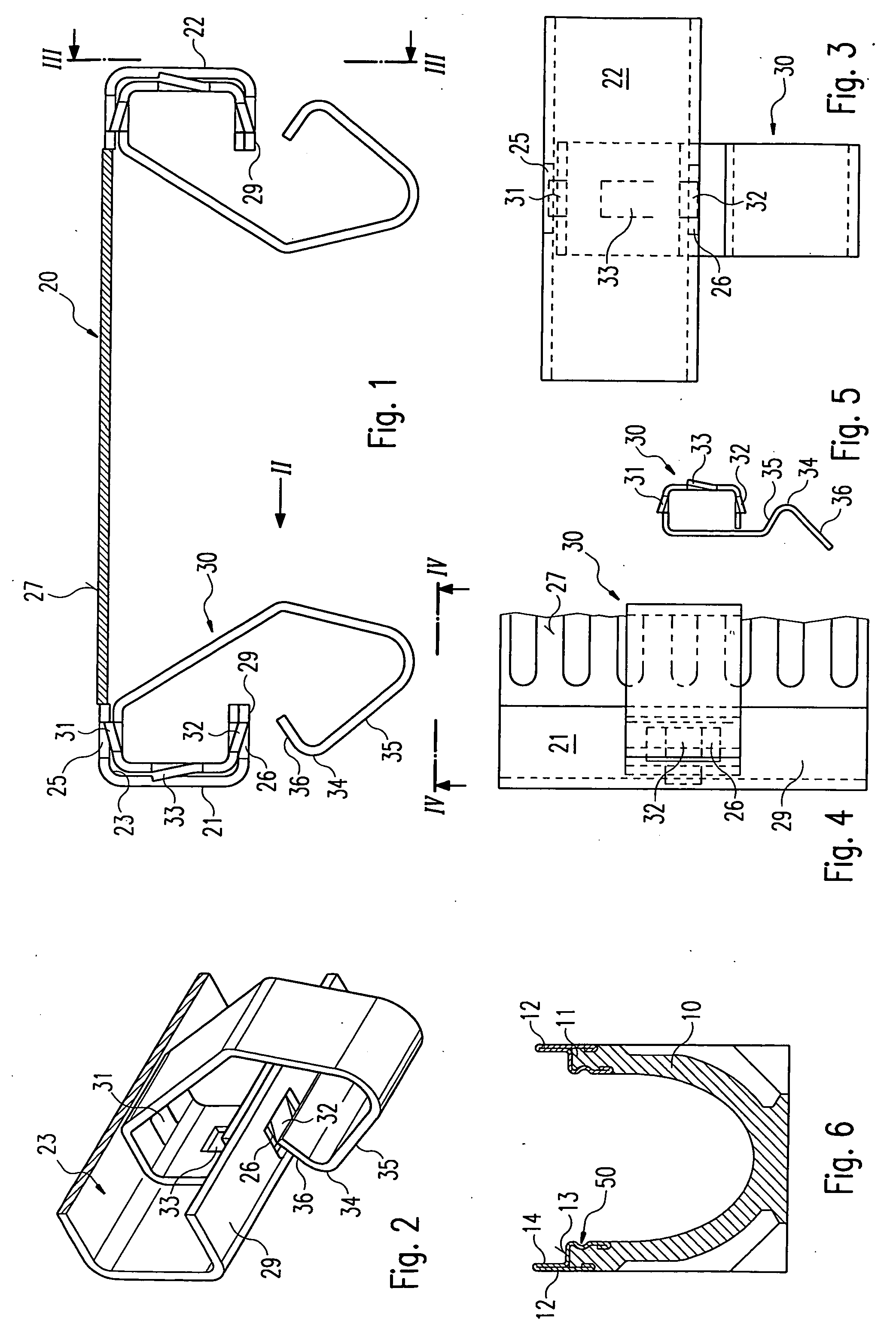
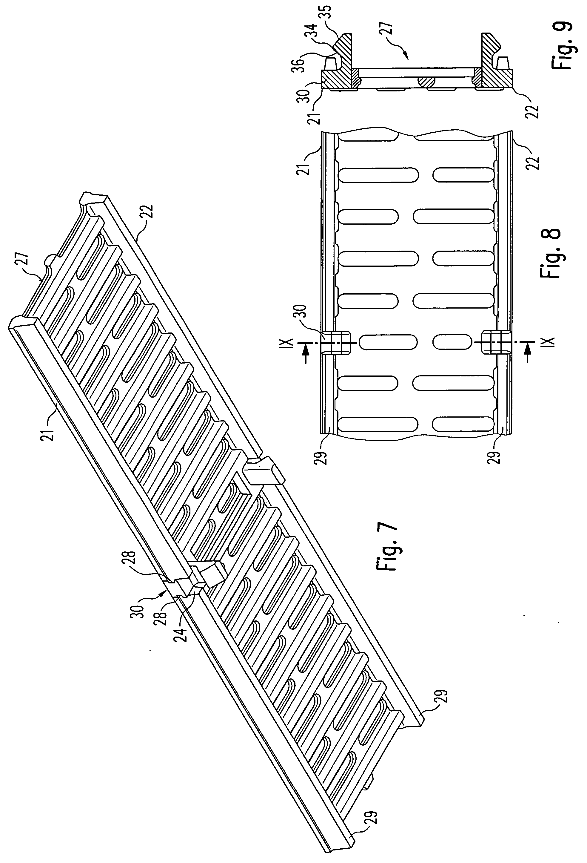
[0037] In the arrangement shown in FIGS. 1 to 4 the cover 20 has been shaped by bending sheet steel. The edges 21, 22 in this case form undercut sections 23, each of which has a U-shaped profile with a supporting rim 29 on its lower side. The cover 20 is laid into a drainage channel such as is shown in FIG. 6, in such a way that the edges 21, 22 are apposed to inner surfaces of lateral folds 14, which are formed by frames 12 that are attached to or poured into the upper edges 11 of a structure 10 that can be installed in the ground. The frames 12 additionally form bearing surfaces 13 on which the cover 20 rests, by way of its supporting rims 29.

[0038] Within the undercut sections 23 hook elements 30 are disposed, to serve as first locking means. In the region where they are situated the contour (in cross section) of the hook elements 30 is identical to the...


PUM


Abstract

A surface water drainage system is provided that comprises a structure that can be installed in the ground, and a cover that can be laid onto an upper edge of said structure. Fixation devices are provided that are attached to the cover and comprise a locking means in the form of elastic hook elements fixed to edges of the cover that can be brought into snap-on engagement with other locking means on said structure in order to retain the cover on the structure.

Description

RELATED U.S. APPLICATIONS [0001] Not applicable. STATEMENT REGARDING FEDERALLY SPONSORED RESEARCH OR DEVELOPMENT [0002] Not applicable. REFERENCE TO MICROFICHE APPENDIX [0003] Not applicable. FIELD OF THE INVENTION [0004] The invention relates to a surface water drainage system, in particular a drainage channel. BACKGROUND OF THE INVENTION [0005] A surface water drainage system of this kind is known, for example, from the documents CH 681 313 or DE 195 11 788 A1. [0006] The problems generally encountered with such drainage systems, in particular drainage channels, are associated with the fact that on one hand the cover lying on the structure installed in the ground must be fixed in position so firmly that even the impulse-like forces encountered when a vehicle travels over the covers cannot release them. On the other hand, the covers must be opened at regular intervals so that cleaning and maintenance work can be done. [0007] In the above-mentioned known surface water drainage syste...

Claims


Application Information

Patent Timeline
IPC IPC(8): E01C11/22E01F5/00E03F5/06
CPCE03F5/06E03F2005/065
Inventor MESSERSCHIMIDT, HEINOSIEBER, MICHAELBLASCHKE, MARKUSSTOLTENBERG, ARNE
Owner ACO SEVERIN AHLMANN GMBH & CO KG
Why Eureka
Try Eureka