Fluid supply assembly with measuring guide

a technology of measuring guide and flue gas, which is applied in the direction of identification means, instruments, machines/engines, etc., can solve the problems of not being able to “zero” the measuring guide, prone to errors, and requiring more refilling

Active Publication Date: 2006-08-17
ILLINOIS TOOL WORKS INC +1
View PDF99 Cites 27 Cited by
  • Summary
  • Abstract
  • Description
  • Claims
  • Application Information

AI Technical Summary

Problems solved by technology

With these designs, a problem arises when the disposable cups are refilled before they have been completely emptied.
There is no way to “zero” the measuring guide to add more paint.
This makes refilling more difficult and subject to errors because the user must remember the “zero” point and adjust the guide's numbers.

Method used


Image

  • Fluid supply assembly with measuring guide
  • Fluid supply assembly with measuring guide
  • Fluid supply assembly with measuring guide

Examples


Embodiment Construction

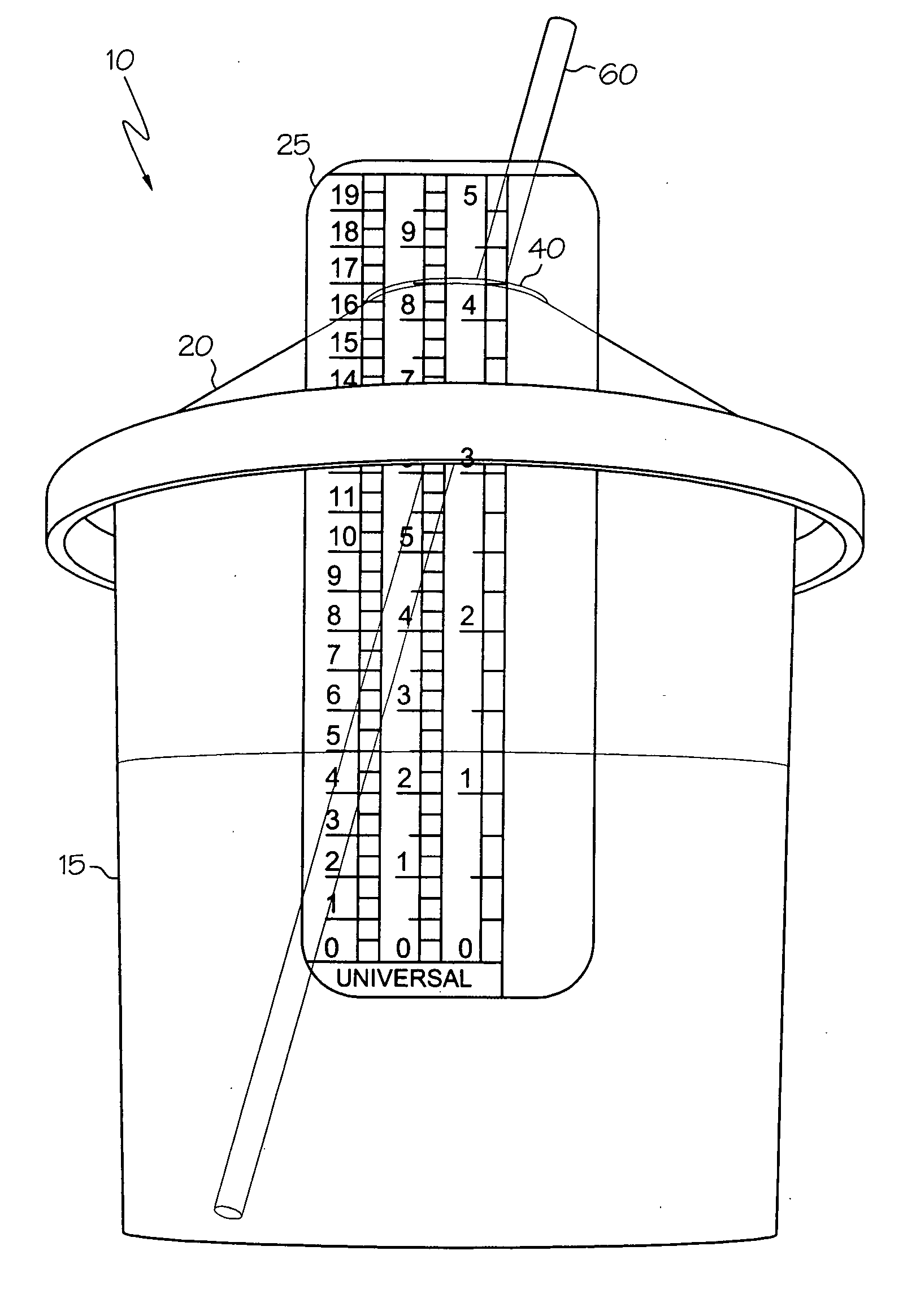
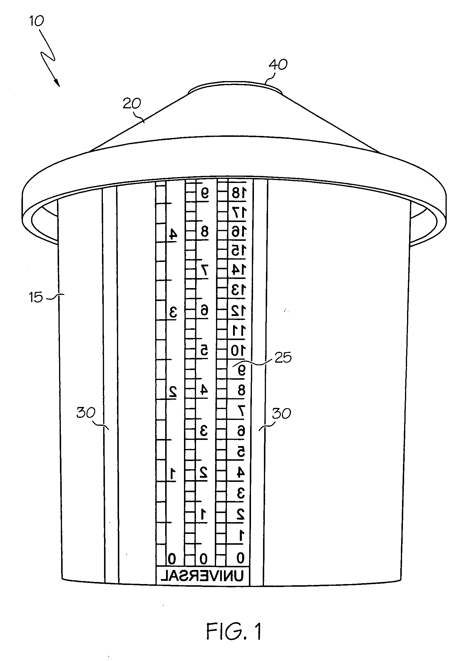
[0017]FIG. 1 shows a fluid supply assembly 10. The fluid supply assembly includes a fluid container 15 and a lid 20. The lid 20 can be attached to the fluid container 15 using any suitable type of connection. Suitable connections include, but are not limited to, threaded connections, lugs and grooves, and pins and slots.

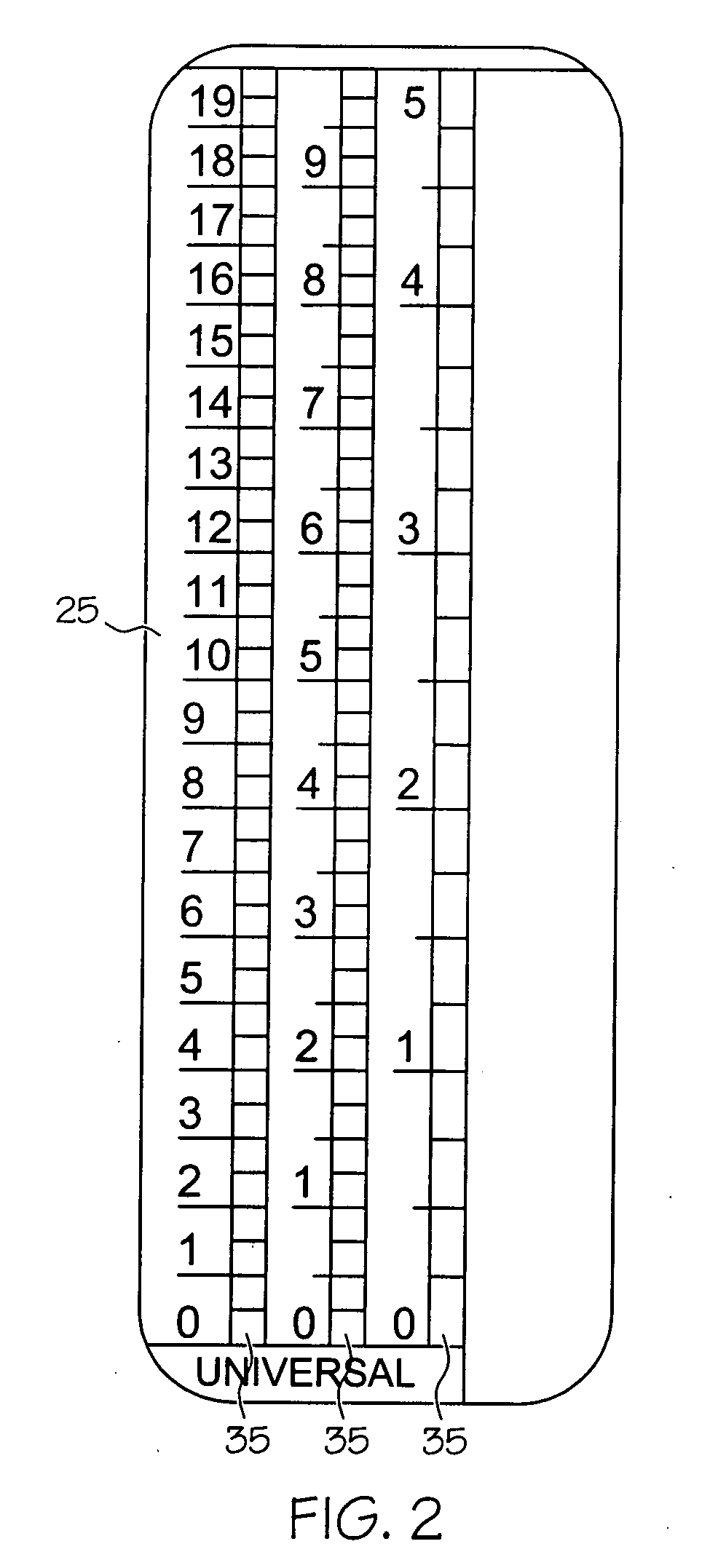
[0018] The measuring guide 25 is attached to the fluid container 15 in a manner which allows it to be moved from a first vertical position on the fluid container to a second vertical position. The channels 30 form a groove into which the measuring guide 25 fits. The channels 30 can extend outward from the side of the fluid container 15 to form the groove. Alternatively, a groove can be formed as an indent in the side of the fluid container. The measuring guide can be attached using other types of attachment allowing movement from one position to another, including, but not limited to, tabs and slots, pins and holes, pressure sensitive adhesive, static charge, etc.

[...


PUM


Abstract

A fluid supply assembly having a measuring guide comprising a fluid container, a lid, and a measuring guide. A method of measuring fluid components in a fluid supply assembly is also described.

Description

CROSS REFERENCE TO RELATED APPLICATION [0001] This patent application claims the benefit of U.S. Provisional Application Ser. No. 60 / 648,478.BACKGROUND OF THE INVENTION [0002] The present invention is directed generally to a measuring guide for fluid components, and more particularly to a fluid supply assembly including a measuring guide for measuring components of a fluid in the fluid container for a fluid applicator. [0003] Paint compositions for automotive refinishing often contain multiple components. The various components are measured, and then the mixture is poured into the spray gun's paint reservoir (commonly called the paint cup). Historically, the components were measured either on a scale, with a measuring cup, or with a measuring stick. The use of the scale allowed accurate measuring of the components, but the amounts needed had to be calculated, either by hand or by computer. The components were weighed in a mixing cup from which they were transferred to the paint cup....

Claims


Application Information

Patent Timeline
Patent Type & Authority Applications(United States)
IPC IPC(8): G09F9/00G01F23/00
CPCB01F13/002B01F15/00506B01F2215/005B44D3/08G01F19/00G01F23/02G01F23/04B05B7/2408B01F33/5011B01F35/3202B01F2101/30
Inventor KOSMYNA, MICHAELWISNIEWSKI, RALPH
Owner ILLINOIS TOOL WORKS INC
Why Eureka
Try Eureka