Variable speed drive for a continuously variable transmission
- Summary
- Abstract
- Description
- Claims
- Application Information
AI Technical Summary
Benefits of technology
Problems solved by technology
Method used
Image

Examples
Embodiment Construction
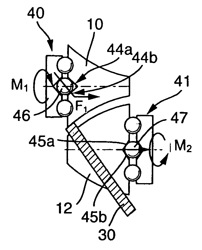
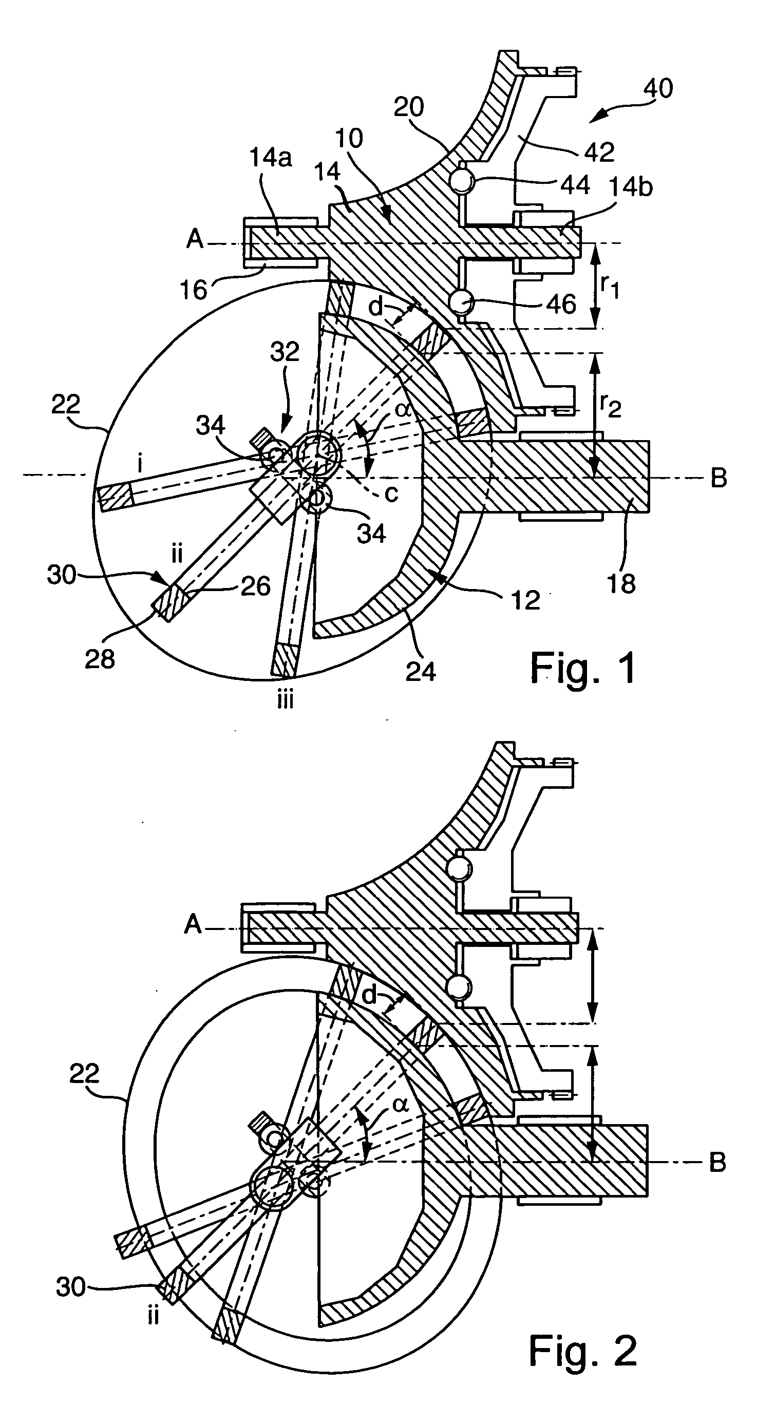
[0032]FIG. 1 shows a longitudinal cross-sectional view through a variable speed drive in a plane that contains two parallel axes of rotation A and B of two transmission elements 10 and 12. Transmission element 10 has stub shafts 14a and 14b that are mounted in a transmission case 16 and that form the driven or input shaft 14 of the variable speed drive.
[0033] Transmission element 12 has a shaft 18 that is mounted in the transmission case and forms the output shaft of the variable speed drive.
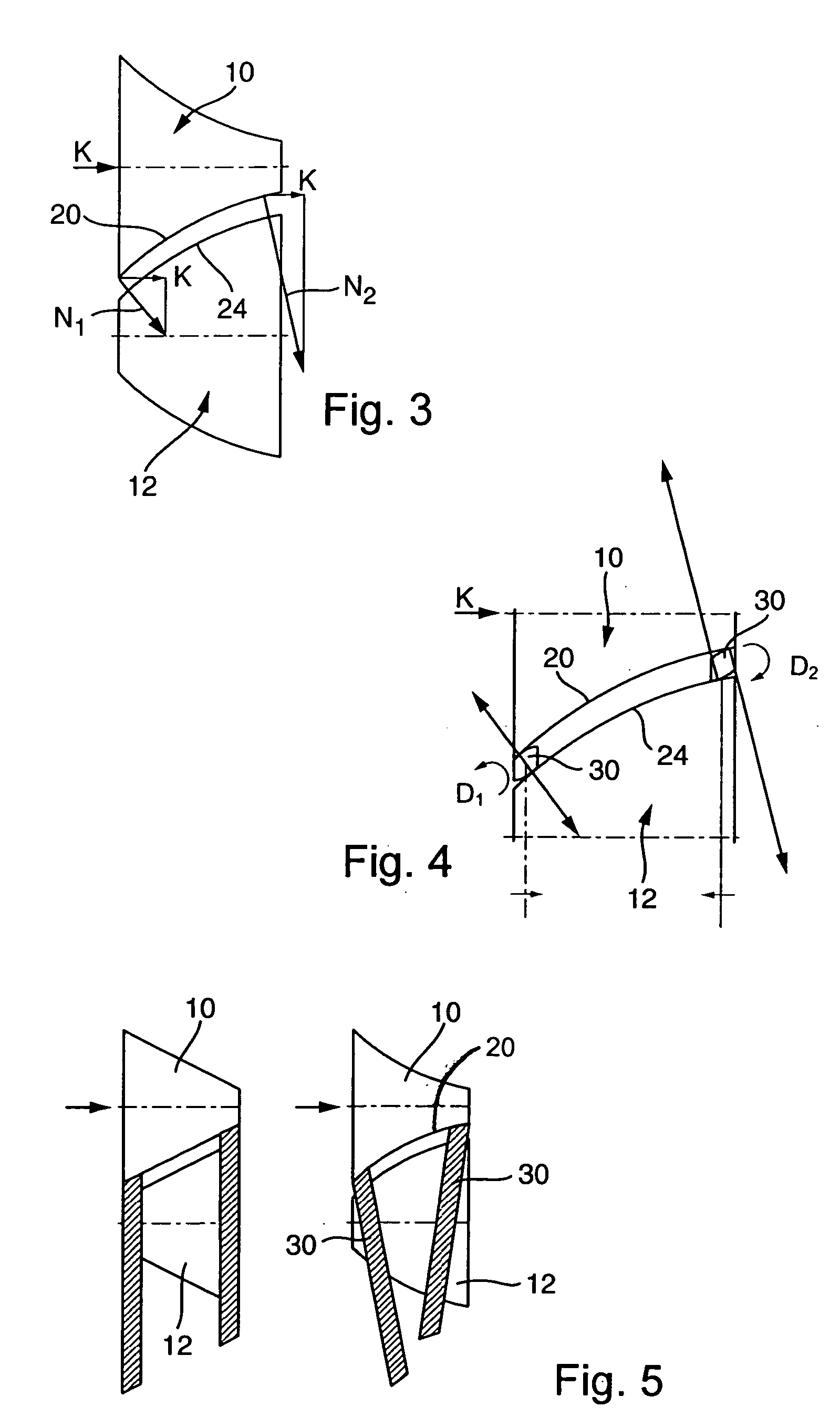
[0034] Transmission element 10 is designed with a concavely curved transmission surface 20, whose profile line in the example shown is part of an ellipse 22.
[0035] Transmission element 12 is designed with a convex transmission surface 24 that is also part of an ellipse.
[0036] As can be seen from FIG. 1, transmission surfaces 20 and 24, that are rotationally symmetrical around their respective axes, are positioned in such a way that the areas of the transmission surfaces that face each other ...
PUM
 Abstract
Description
Claims
Application Information
 - R&D Engineer
- R&D Manager
- IP Professional
- Industry Leading Data Capabilities
- Powerful AI technology
- Patent DNA Extraction
Browse by: Latest US Patents, China's latest patents, Technical Efficacy Thesaurus, Application Domain, Technology Topic.
© 2024 PatSnap. All rights reserved.Legal|Privacy policy|Modern Slavery Act Transparency Statement|Sitemap