Method and apparatus for producing an index vector for use in performing a vector permute operation

a vector and permutation operation technology, applied in the field of vector operations, can solve problems such as insufficient support of data-based permutation operations

Active Publication Date: 2006-08-17
TEXAS INSTR INC
View PDF9 Cites 72 Cited by
  • Summary
  • Abstract
  • Description
  • Claims
  • Application Information

AI Technical Summary

Problems solved by technology

These data-based permutation operations are not supported well on existing SIMD arc

Method used


Image

  • Method and apparatus for producing an index vector for use in performing a vector permute operation
  • Method and apparatus for producing an index vector for use in performing a vector permute operation
  • Method and apparatus for producing an index vector for use in performing a vector permute operation

Examples


Embodiment Construction

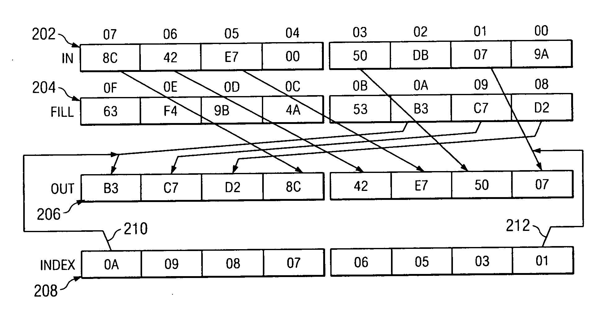
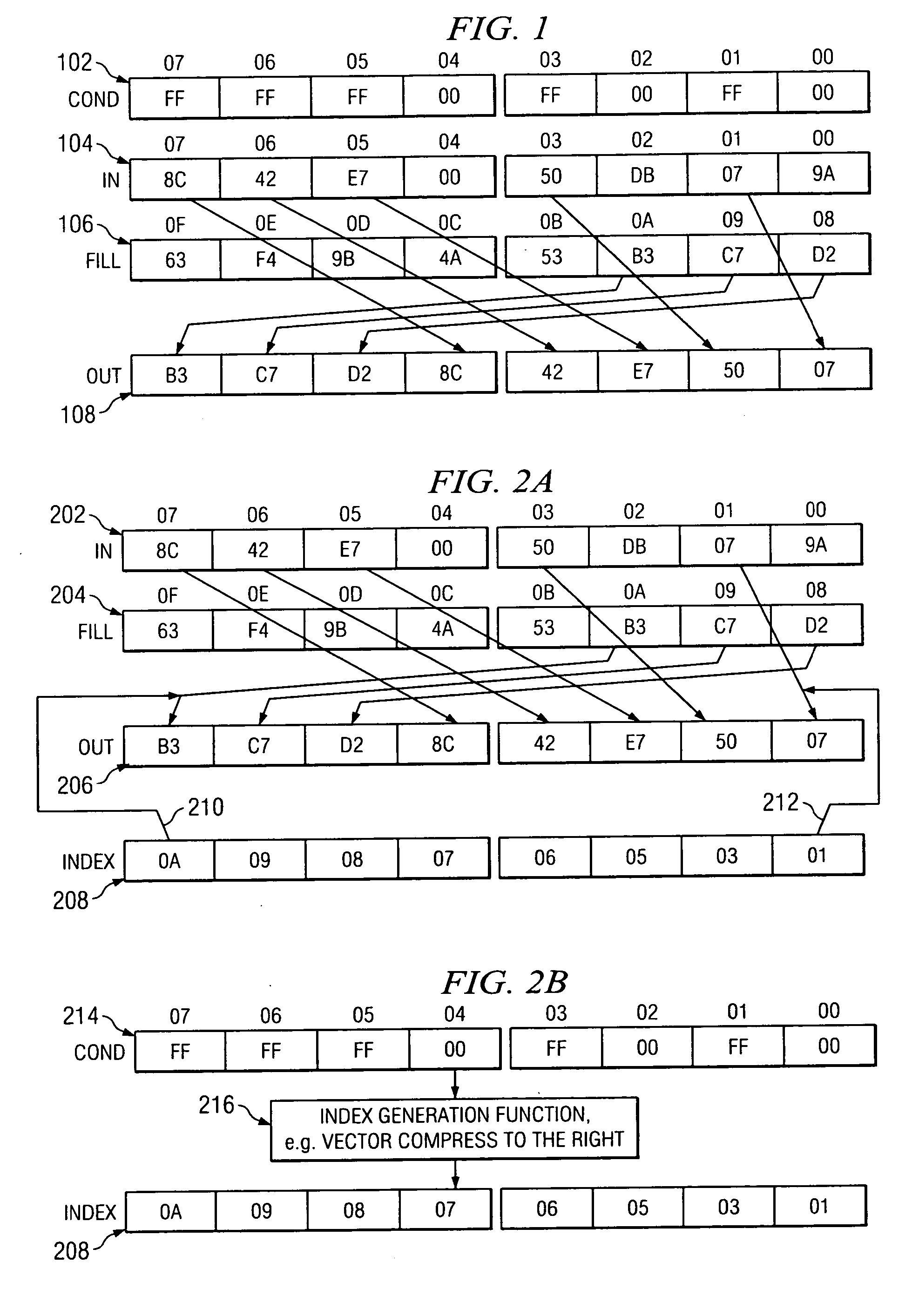
[0012] Referring to FIG. 1, there is shown the results of a vector compress (compression) process in accordance with an embodiment of the invention. A condition (cond) register 102 selects which bytes of a first or “in” vector 104 are to be compressed into a second or “out” vector 108. The values stored in the condition register 102 can be the result of some type of comparison such as a vector compare or other operation previously performed within a system. The locations in the “in” register 104 that correspond to the byte locations (e.g., in this example locations 0-7) in the condition register 102 having an “FF” or “true” condition state are transferred to the rightmost byte of the out register 108 not yet filled by some other byte of the “in” register to the right of this byte in the “in” register. Those byte locations in the condition register 102 having a “00” or “false” condition states are not transferred to the out register 108. As an optional feature and in order to provide...


PUM


Abstract

A method for generating a permutation index vector includes receiving a condition vector and performing an index generation function using the condition vector in order to generate the permutation index vector. An index vector generation circuit is also disclosed.

Description

FIELD OF THE INVENTION [0001] The invention relates in general to the field of electronics and more specifically to vector operations. BACKGROUND OF THE INVENTION [0002] Vector computers perform operations on each element of a vector. For example, the corresponding elements of two vectors can be added to produce a vector of sums. Single Instruction Multiple Data (SIMD) architectures perform vector operations on several data elements in parallel. This is sometimes referred to as short vector architecture. [0003] Permutation operations can reorder the elements of a vector under the control of a permutation index vector. For example, the elements of a vector can be reversed by permuting the first element to last, etc. [0004] Some high level operations require the selection of a permutation based on data available to a program. For example, the permutation that sorts a vector depends on the relative magnitudes of the vector elements themselves. These data-based permutation operations ar...

Claims


Application Information

Patent Timeline
IPC IPC(8): G06F15/00
CPCG06F7/76G06F7/764G06F9/30032G06F9/30036G06F15/8084
Inventor KRUEGER, STEVEN D.
Owner TEXAS INSTR INC
Why Eureka
Try Eureka