Filter apparatus

a filter and liquid technology, applied in the field of filter apparatuses, can solve the problems of less than satisfactory filter apparatuses in providing such needs, desired features and functionality, and achieve the effect of facilitating tool-less removal

Active Publication Date: 2006-08-24
BALDWIN FILTERS
View PDF84 Cites 142 Cited by
  • Summary
  • Abstract
  • Description
  • Claims
  • Application Information

AI Technical Summary

Benefits of technology

[0016] Where the filter element and filter base include complimentary keyed axial projections, the complimentary, keyed, ramp-like structures between the housing and the filter base, and between the element and the housing, ensure that the keyed axial projections on the element and the filter base engage properly. Where the base includes a flow control valve, these various keyed structures are preferably configured such that the axial projections on the filter element engage the projections on the valve, with the valve in the closed position, when the filter cartridge formed by the combined element and housing are inserted in a linear direction into the filter base, with the keys between the housing and base aligned. The cartridge is then turned a predetermined angle, such as ¼ or ½ turn, to cause the second set of complimentary, keyed, ramp-like structures between the housing and the filter base to engage and pull the cartridge into sealed engagement with the filter base, while simultaneously turning the valve from the closed to the open position. The cartridge may then be locked into position, using the drain valve apparatus, or other locking means such as a locking collar, locking pins, or toggle bolts, etc.

Problems solved by technology

Previous filter apparatuses have been less than satisfactory in providing such needs, desired features and functionality.

Method used


Image

  • Filter apparatus
  • Filter apparatus
  • Filter apparatus

Examples


Embodiment Construction

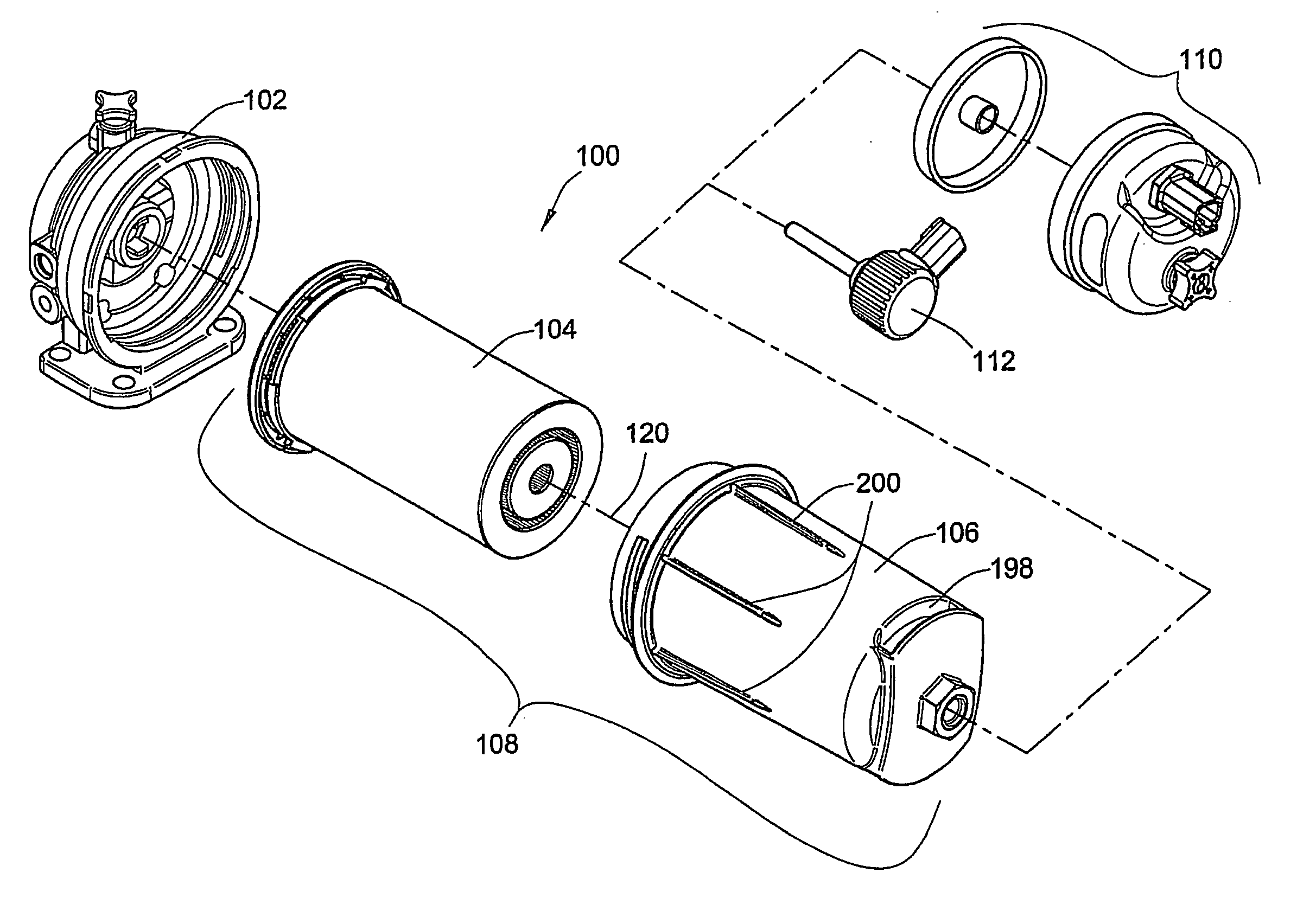
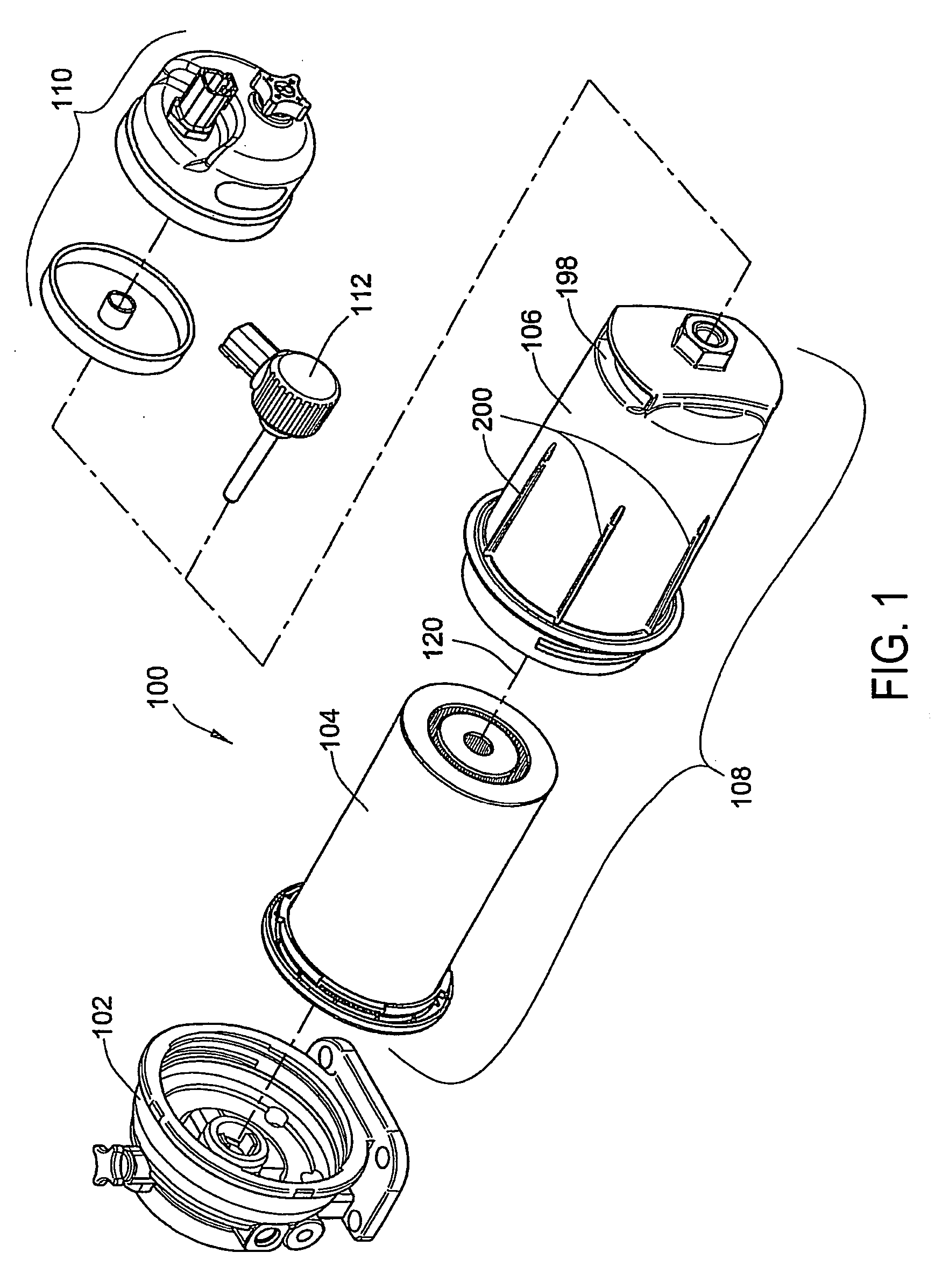
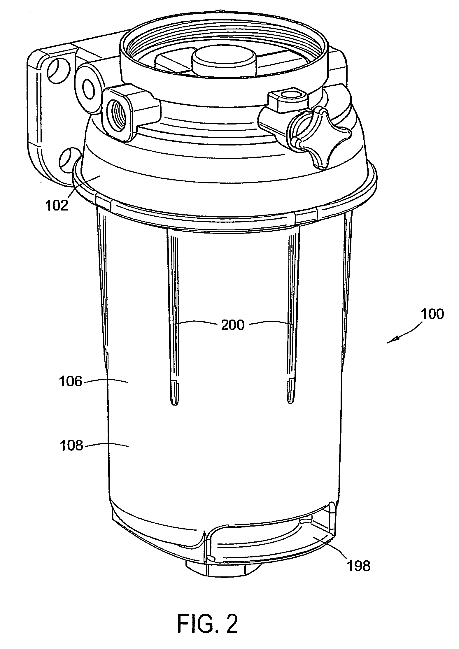
[0070]FIGS. 1-3 show an exemplary embodiment of a filter apparatus 100, according to the invention, including a filter base 102, a filter element 104, and a filter housing 106. As shown generally in FIG. 1, and described in more detail below, the element 104 and housing 106 are configured to be joined together, to form a filter cartridge 108, which is then sealingly joined to the base 102. A filter apparatus, according to the invention, may also include additional components, such as the fluid pre-heater 112, or the water separator 110 shown in FIG. 1.

[0071] As shown in FIGS. 4-8, the filter element 104 includes inner and outer substantially tubular-shaped media packs 114, 116 disposed about a longitudinal axis 118 of the filter element that will be aligned with a longitudinal axis 120 of the exemplary embodiment to the filter apparatus 120, as indicated in FIG. 1. The filter element 104 also includes a first end cap 122, an outer seal 123, an inner seal 125, second end caps 130, 1...


PUM

PropertyMeasurementUnit
forcesaaaaaaaaaa
timeaaaaaaaaaa
forceaaaaaaaaaa

Abstract

A fluid filtering apparatus and method may include keyed components to ensure that a correct filter element is being installed into a filter base, and to automatically actuate a fluid valve as the filter element is rotated into place on the base. Tool-less replacement of the element is provided. An embodiment of the element may include inner and outer substantially tubular-shaped media packs disposed about an axis, with one end of each of the inner and outer media packs being attached to an end cap of the element in a manner defining a fluid flow space between the inner and outer media packs for receiving a flow of fluid directed in parallel through the inner and outer media packs. A housing of the filter apparatus may include a flow tube configured to fit into the space between the inner and outer media packs.

Description

CROSS-REFERENCE TO RELATED APPLICATIONS [0001] This patent application claims the benefit of U.S. Provisional Patent Application No. 60 / 655,178, filed Feb. 22, 2005, which is incorporated herein in its entirety.FIELD OF THE INVENTION [0002] This invention relates generally to filtering and separating liquids, and more particularly to filter apparatuses of the type used for the fuel supply of an engine or for the lubrication system of an engine. BACKGROUND OF THE INVENTION [0003] It is necessary to remove particulate matter and water from fuel being supplied to an engine in order for the engine to operate properly and to have a long service life. Accordingly, the fuel supply system for an engine will typically include a fuel filter apparatus for removing particulate matter from the fuel before it is supplied to the engine. Such filter apparatuses also sometimes include provisions for removing water from the fuel, pre-heating the fuel, and provisions for injecting anti-gel or lubricit...

Claims


Application Information

Patent Timeline
Patent Type & Authority Applications(United States)
IPC IPC(8): B01D35/153
CPCB01D29/118B01D29/21B01D35/147B01D36/003B01D37/025B01D2201/0407B01D2201/0415B01D2201/12B01D2201/127B01D2201/28B01D2201/295B01D2201/305B01D2201/40B01D2201/4015B01D2201/4046B01D2201/4084B01D2201/52B01D2201/60B01D29/232B01D29/54B01D35/153B01D35/16
Inventor FICK, WALTER J.BEARD, JOHN H.MARSHALL, JAMES N.QUACKENBUSH, JOSHUA L.
Owner BALDWIN FILTERS
Why Eureka
Try Eureka