
Programmable wall switch controller

a technology of programmable switch levers and controllers, which is applied in the direction of switch power arrangements, tumbler/rocker switch details, and sustainable buildings, etc., can solve the problems of increasing the normal operating power consumption of geared dc motors, and achieves accurate and correct alignment, easy installation and convenient use

Inactive Publication Date: 2011-12-27
MANTOURA PAUL MR
View PDF5 Cites 47 Cited by
  • Summary
  • Abstract
  • Description
  • Claims
  • Application Information

AI Technical Summary

Benefits of technology

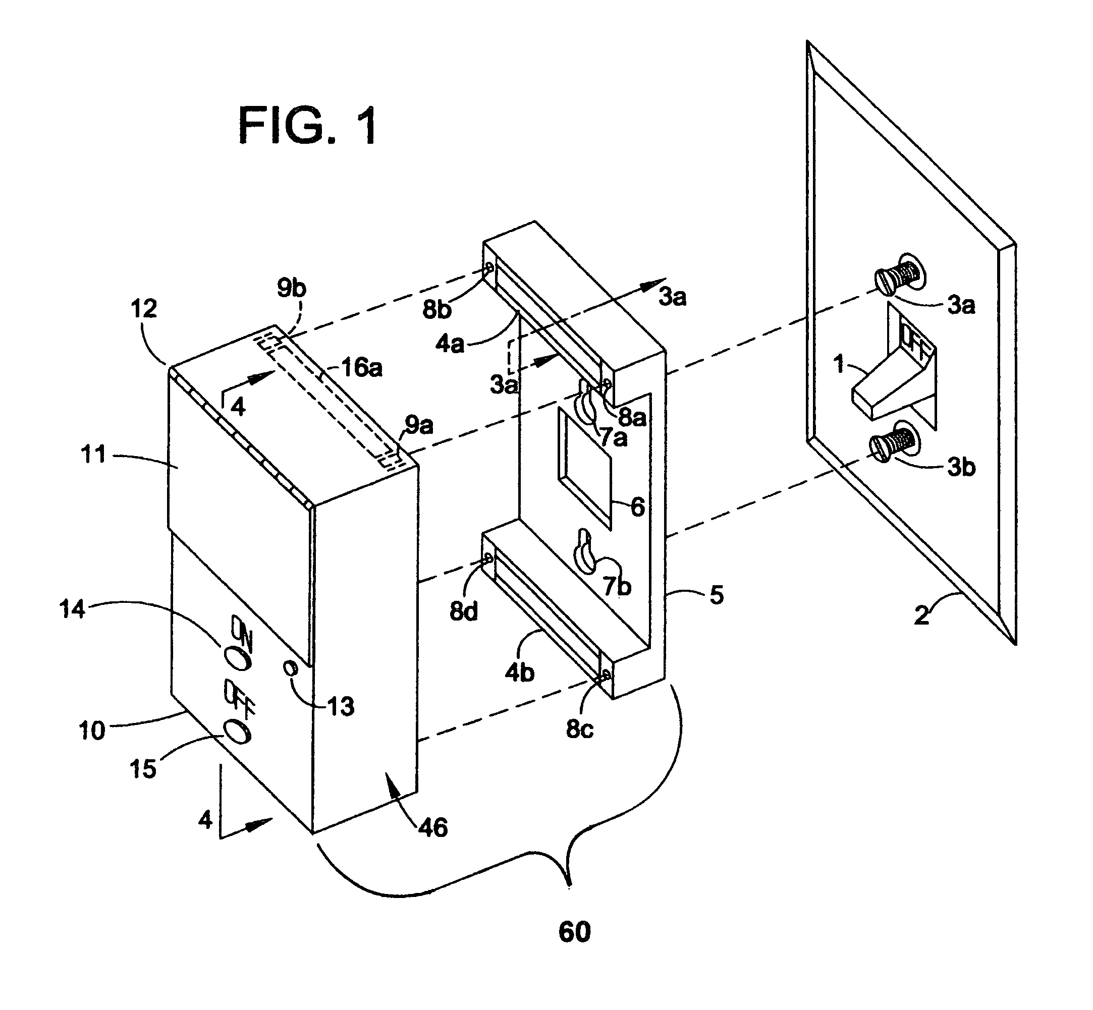
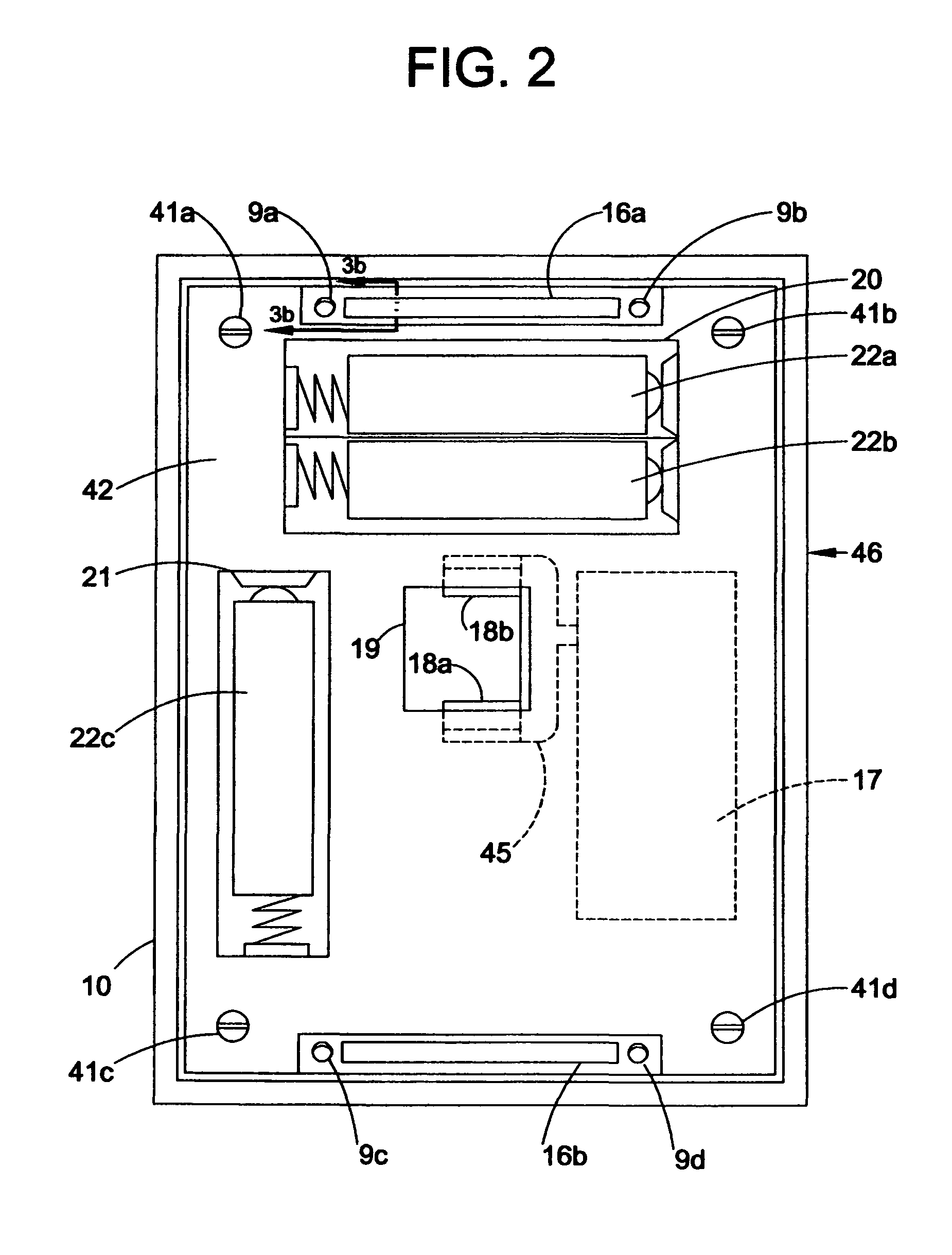
In its preferred embodiment, the subject invention overcomes the disadvantages and limitations of the above referenced patents. The present invention provides a switch cover plate with an electrical timer means that activates the switch lever to its On position and to its Off position at predetermined intervals of time. Further, the present invention provides a switch cover plate with an electrical timer means that is easily installed and provides a means to accurately and properly align the actuator means with the switch lever arm. The subject invention provides a self-contained programmable timer device with a housing that fits over the standard switch cover plate. The housing contains a horseshoe shaped cam to directly engage the switch lever and the same cam is used to directly disengage the switch lever. Rotational motion of the cam in the forward direction moves the switch lever from its Off position to its On position and rotational motion of the cam in the reverse direction moves the switch lever from its On position to its Off position. Rotational motion of the cam is provided by an electromechanical means comprising a miniature geared DC motor. There is no return spring mechanism and there are no springs, latches, or catches. The wall switch is allowed to latch and catch itself in both directions. The timer has a power supply comprised of built-in batteries and has its own crystal time-base. Programming and control means are provided by the use of a microprocessor and motor power driver circuitry. The forward and reverse operations of the geared DC motor are controlled by the programming and control means which provides power from the batteries to the geared motor in accordance with a pre-settable 24 hour program. Both operations are performed electrically and electronically, no manual operation is needed to initiate either operation, and several On-Off intervals can be programmed. Program information such as present time and time occurrences for several On-Off intervals may be entered and modified by way of pushbuttons and switches contained on the front cover of the device. An indicator light is used for the indication of low voltage and for the need to replace the batteries, for indication of correct inputting of timing information, and for indication of the number of On-Off cycles successfully entered. Further, there is a switch means to allow temporary suspension of the timer operation without loss of the pre-stored programming information. This allows the timer operation to be restored without the need for re-programming.
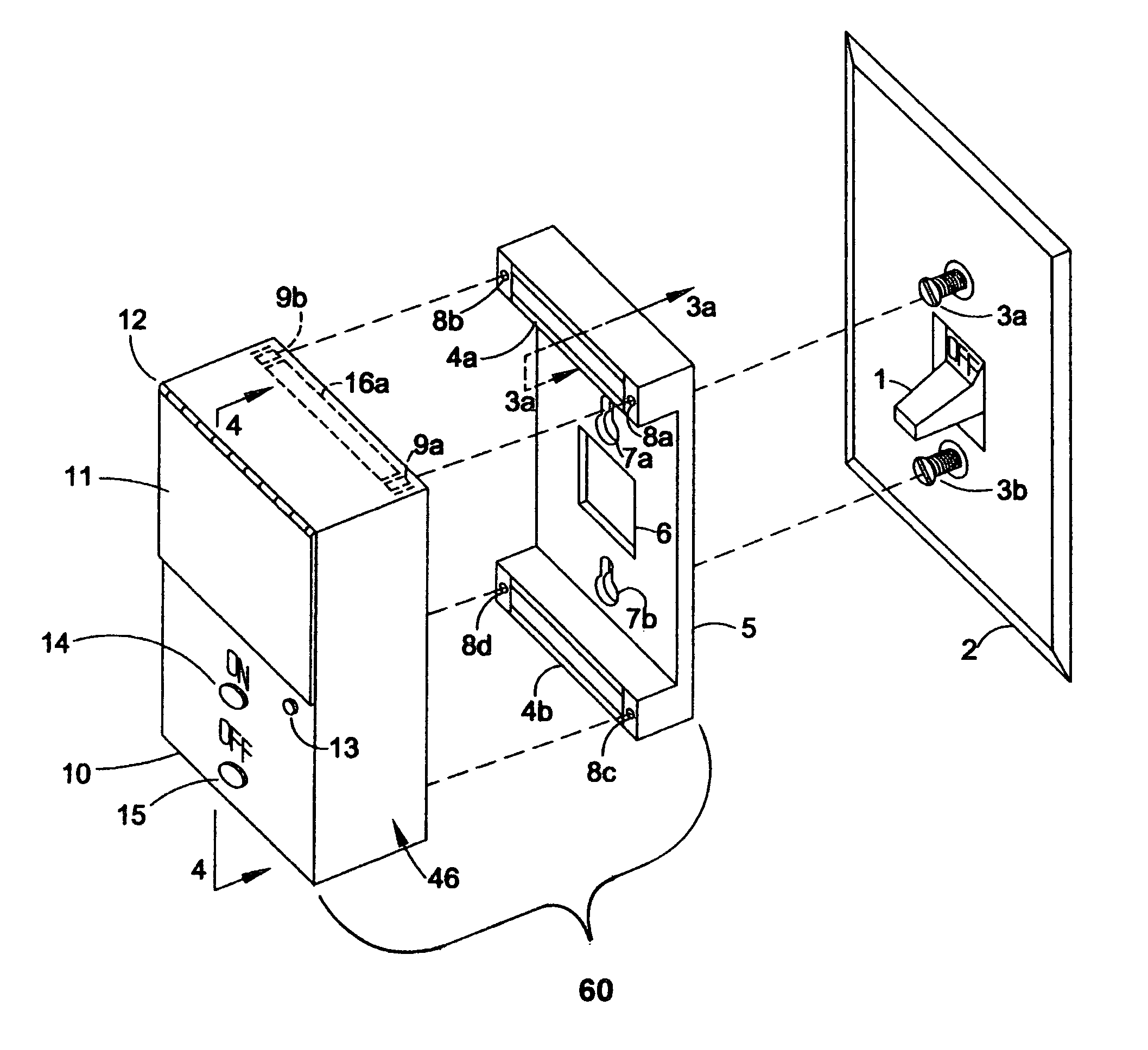
Further, the present invention achieves proper actuation of the switch by providing accurate positioning and alignment of the device cam arms with the existing switch lever arm. This is accomplished by the use of a key-holed alignment plate. First, both cover plate screws are loosened, then the alignment plate is installed over the existing switch cover plate. The alignment plate keyholes lineup with the existing mounting screw holes of the cover plate and then both of the cover plate screws are tightened to fasten the alignment plate to the cover plate. This approach takes advantage of the fixed relationship between the cover plate screw holes, the switch lever arm, and the opening in the cover plate for the switch lever arm. The alignment plate has two mounting channels and the device housing has complementary shaped mounting strips that are designed to fit into the mounting channels. The device housing then snaps into the alignment plate and this ensures correct alignment and engagement of the device cam arms with the switch lever arm. The mounting channels and mounting strips provide a secure mechanical connection and provide fast and easy attachment and removal of the device housing to the alignment plate.
In addition, the present invention allows for direct manual operation of the exiting switch. Manual operation of the existing switch lever is achieved by use of an easily accessible lever arm that protrudes from the front of the device housing. The extended lever arm of the device is connected directly to the cam and is used to move the cam mechanically to activate and deactivate the switch under control. An optional design of the present embodiment provides for the manual activation of the existing switch electrically by the use of pushbuttons on the front surface of the device housing. The pushbutton switches activate the electromechanical means which moves the cam to activate and deactivate the switch under control. In this embodiment, no external lever arm is needed and the front housing of the device can be sealed.
The present invention also provides a means to limit the power consumption of the geared DC motor thereby extending battery life. This is provided by two different means. The microprocessor is programmed to activate the geared DC motor at the beginning of the stored On-Off time intervals. The microprocessor is further programmed to activate the geared DC motor for only a short period of time such as a few seconds. This activation time is sufficient to allow the cam arm to move the switch lever arm to its end-of-travel positions. After the switch lever arm has reached its end-of-travel positions, there is no need to continue applying power to the geared DC motor. Precise control of the amount of rotation and the position of the cam is not needed. In addition, the motor control means has electronic circuitry that is designed to limit the maximum power flow to the geared DC motor during its operation. An increase in normal operating power consumption by the geared DC motor is possible when it is stopped from rotating. This is a motor rotor-lock condition, which occurs when the cam arm moves the switch lever to its end-of-travel position and the switch mechanical stop is encountered. The geared DC motor unit that is used in the present embodiment has a safety clutch mechanism which prevents a rotor-lock condition from occurring.

Problems solved by technology

An increase in normal operating power consumption by the geared DC motor is possible when it is stopped from rotating.

Method used


Image

  • Programmable wall switch controller
  • Programmable wall switch controller
  • Programmable wall switch controller

Examples


third embodiment

FIG. 7 shows a third preferred embodiment of the present invention mounted to a standard switch cover plate cover plate 2. The main housing unit 49 of the third embodiment is comprised of the same back cover 42 in the previous two embodiments and a front cover 50 which is designed to accept a display screen and pushbutton panel module 51. In this embodiment, a standardized display screen and pushbutton panel module 51 is used to display time information and to enter the information into the microprocessor 35 (shown in FIG. 8). The display screen 52 is a standard, segmented, four-digit, 12-hour clock display with a PM indicator light 54. The display screen 52 can be a conventional low power display such as an LCD or OLED type of display. The pushbutton panel 53 has five keys. The PT key 53b, the ON T key 53c, the OFF T key 53d, and the CL key 53e, are used for the same functions as the P-T pushbutton switch 27, the ON-T pushbutton switch 28, the OFF-T pushbutton switch 29, and the CL...

second embodiment

FIG. 8 is also representative of the block diagram of the microprocessor 35 and its electrical interfaces for the For this embodiment, there is no On pushbutton switch 14 and no Off pushbutton switch 15 and the microprocessor 35 does not have the corresponding electrical interfaces to these switches.

FIG. 8 is also representative of the block diagram of the microprocessor 35 and its electrical interfaces for the third embodiment. For this embodiment, the rotary switch 26 electrical interfaces will be replaced by electrical interfaces from the display screen and pushbutton panel module 51.


PUM


Abstract

A programmable switch lever control timer device that fits over a standard wall switch with the switch lever engaged by a cam on the device. Rotational motion of the cam provided by a geared DC motor moves the switch lever arm to one of its two end-of-travel positions of operation. Programming and control means are provided by a microprocessor and motor driver circuitry. The programming and control means provides power from a battery source to the geared DC motor in accordance with a user selectable 24-hour program. Proper and accurate alignment of the switch lever and cam during installation is provided by a key-holed alignment plate that is attached to a standard wall switch cover plate prior to installing the device housing. The housing of the device attaches to the alignment plate allowing the housing to properly fit over the switch lever. All of the operating parts including a self-contained battery power source are within the device housing that fits over the standard wall switch cover plate.

Description

BACKGROUND OF THE INVENTION1. Field of the InventionThe present invention relates to an electronic programmable switch lever control timer that can activate a switch lever arm directly and automatically at preselected adjustable intervals of time to provide for programmable control of the power provided to the load normally controlled from the switch.2. Description of the Prior ArtSeveral types of electronic programmable switch timers are available in the market place and many more types have been described in U.S. patent applications. Most, however, can be characterized as falling into one of two major categories, first, those devices that control the switch lever directly and, second, those devices that replace the switch altogether with another type of device. For example, U.S. Pat. No. 5,828,018 dated Oct. 27, 1998, U.S. Pat. No. 5,306,957, dated Apr. 26, 1994, U.S. Pat. No. 5,465,031 dated Nov. 7, 1995, and U.S. Pat. No. 5,719,362 dated Feb. 17, 1998 fall into the first categor...

Claims


Application Information

Patent Timeline
IPC IPC(8): H01H7/08
CPCH01H3/26H01H23/22H01H2071/006H01H2300/03Y04S20/14Y02B90/224Y02B90/20
Inventor MASSARO, MICHAEL JAMESMASSARO, JOHN DOMINIC
Owner MANTOURA PAUL MR
Learn More