Photomultiplier system and a microscope

Active Publication Date: 2006-08-24
LEICA MICROSYSTEMS CMS GMBH
View PDF1 Cites 0 Cited by
  • Summary
  • Abstract
  • Description
  • Claims
  • Application Information

AI Technical Summary

Benefits of technology

[0006] It is, therefore, an object of the present invention to provide a photomultiplier system and a microscope including a detector tube and a power supply unit for providing the accelerating voltage to operate the detector tube which will enable measurement of even very weak light signals using structurally simple means.
[0008] In accordance with the present invention, it was discovered that the spacing between the detector tube and the power supply unit in a photomultiplier system can indeed be kept small while still preventing, to the extent possible, heating of the detector tube by the power supply unit. Specifically, a thermal isolation element is provided for this purpose between the detector tube and the power supply unit. In other words, the detector tube and the power supply unit are disposed on different sides of a thermal isolation element. The thermal isolation element suppresses heat transfer from the power supply unit to the detector tube, it still being possible to keep the spacing between the detector tube and the power supply unit small in order to reduce external interference and to minimize high-voltage wiring between the power supply unit and the detector tube. Thus, the photomultiplier system of the present invention reduces background noise of the detector tube to the extent possible.
[0009] Therefore, the photomultiplier system provided by the present invention is a photomultiplier system which enables measurement of even very weak light signals using structurally simple means.
[0010] In an especially simple design, the isolation element could be plate-shaped. This, at the same time, allows for effective thermal isolation between the detector tube and the power supply unit.
[0013] Further, in order to provide efficient thermal isolation and to prevent heat conduction from the power supply unit to the detector tube, the support member or the power supply unit could have a plurality of thin coupling elements for coupling to the isolation element and to provide a predeterminable distance between the support member or the power supply unit and the isolation element. In other words, the support member or the power supply unit could be mounted on the isolation element via such thin coupling elements, which make heat conduction more difficult. The length of the coupling elements can be selected according to the desired distance between the support member or the power supply unit and the isolation element.
[0019] In order to prevent unwanted heating of the detector tube, the power supply unit and / or the detector tube could have a cooling device associated therewith. Such a cooling device could be in the form of a passive cooling device. Specifically, the cooling device for the power supply unit could be implemented in the form of a housing cover or housing part or heat sink thermally coupled to the power supply unit. This allows the heat generated by the power supply unit to be dissipated before it is transferred to the detector tube.

Problems solved by technology

In sensitive measurements, i.e., in measurements intended for the detection of weak light signals, it is problematic that the detector tube is often heated by the power supply unit, whereby background noise is generated in the detector tube, said background noise interfering with the measurement and reducing the detection sensitivity of the photomultiplier system.
However, the reduction in spacing in turn increases the risk for the detector tube to be heated by the power supply unit.

Method used


Image

  • Photomultiplier system and a microscope
  • Photomultiplier system and a microscope
  • Photomultiplier system and a microscope

Examples


Embodiment Construction

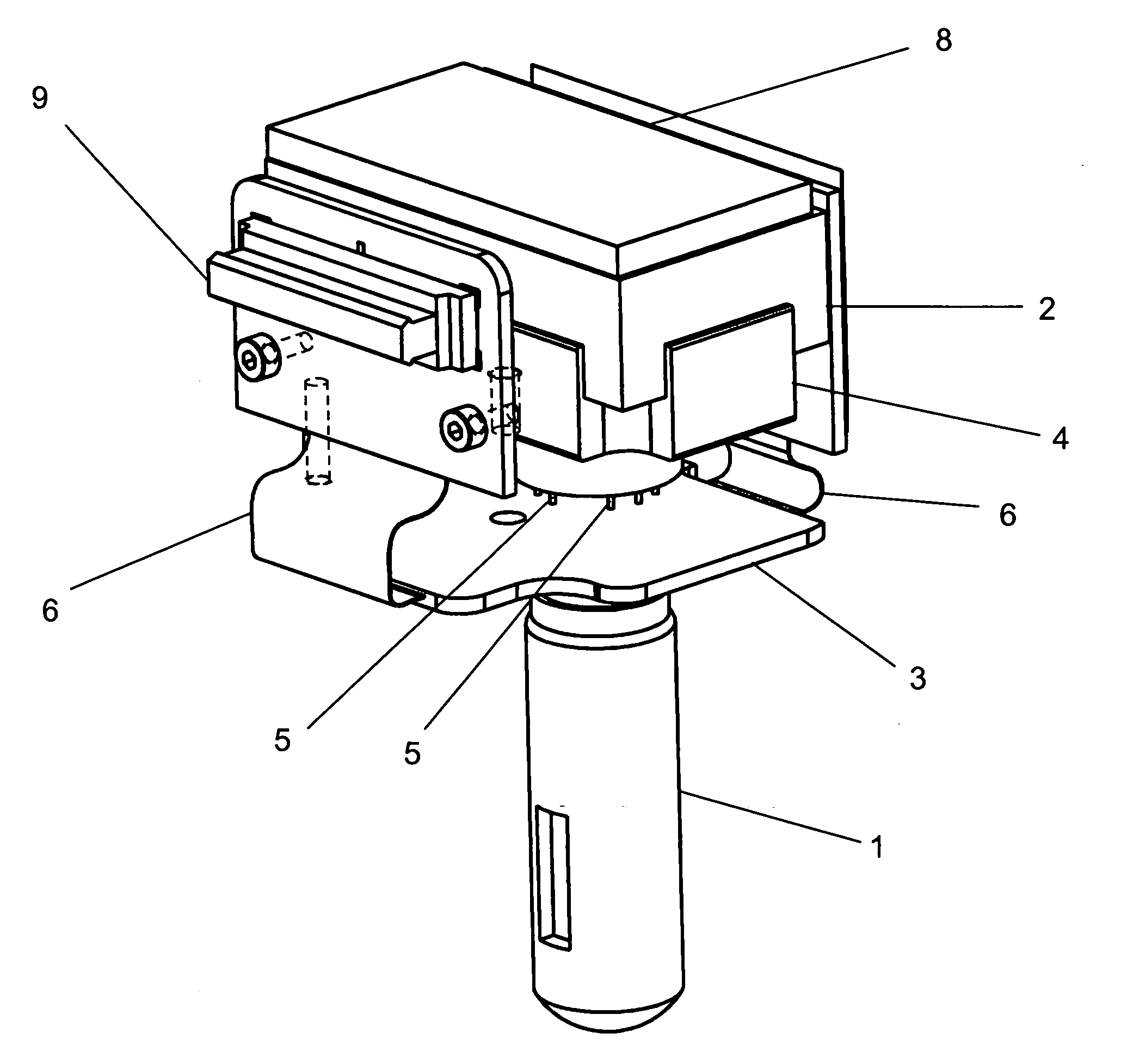
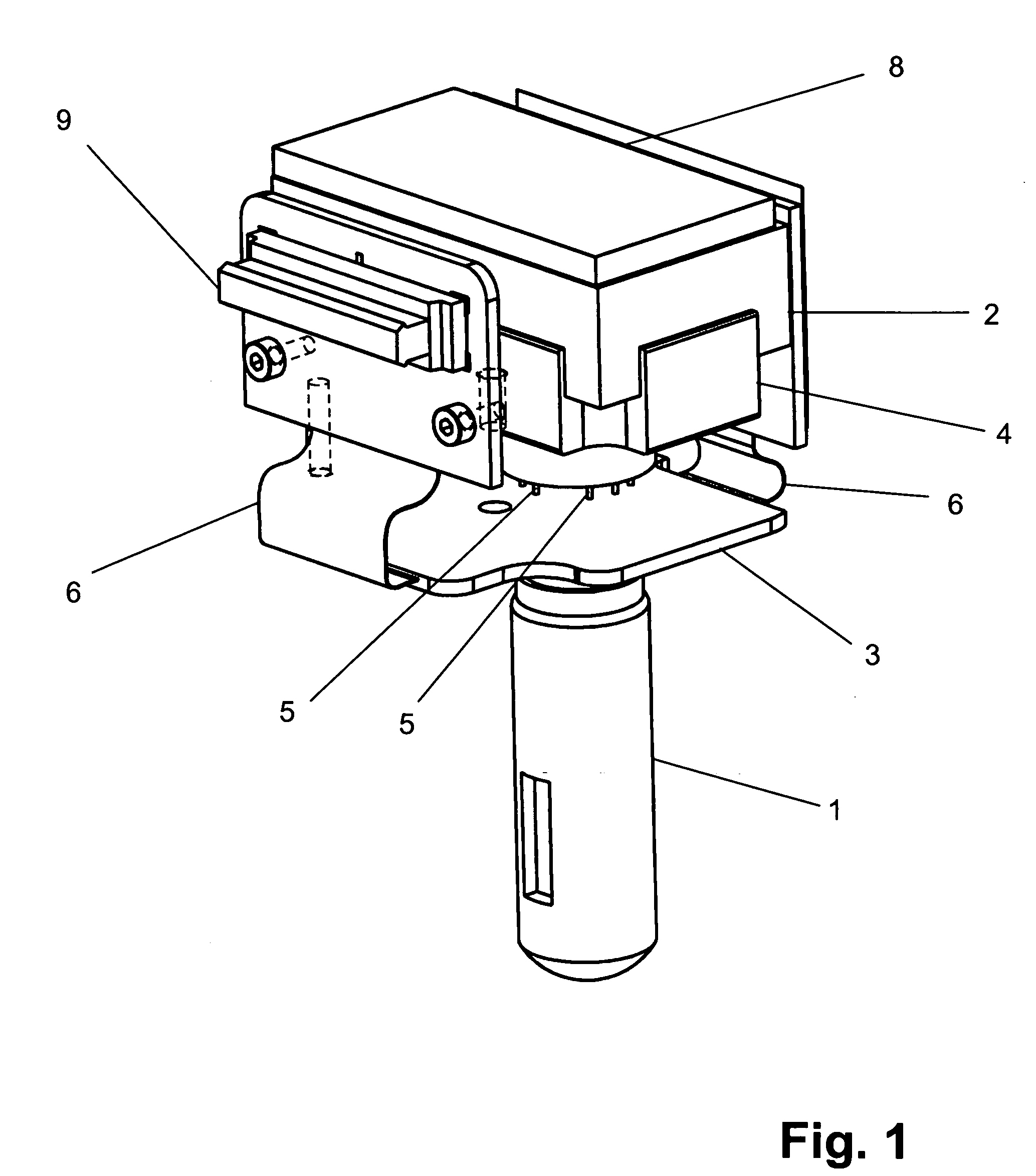
[0027]FIG. 1 is a perspective side view of an exemplary embodiment of a photomultiplier system of the present invention, including a detector tube 1 and a power supply unit 2 for providing the accelerating voltage required to operate detector tube 1. In order to enable detection of even very weak light signals using structurally simple means, detector tube 1 and power supply unit 2 are disposed on different sides of a thermal isolation element 3.

[0028] Power supply unit 2 is mounted on a support member 4, which provides a barrier against heat radiation from power supply unit 2 toward isolation element 3 and detector tube 1. The coupling of power supply unit 2 to isolation element 3 is mainly via support member 4. In order to prevent significant heat transfer, support member 4 has a plurality of thin coupling elements 5 in the form of straps for coupling to isolation element 3. In this manner, a predeterminable distance is provided between power supply unit 2 and isolation element 3...


PUM


Abstract

A photomultiplier system includes a detector tube, a power supply unit, and a thermal isolation element. The power supply unit provides an accelerating voltage for operating the detector tube. The detector tube and the power supply unit are disposed on different sides of the thermal isolation element.

Description

[0001] Priority is claimed to the provisional application entitled “Photomultiplier System and Microscope,” filed by applicants on Feb. 8, 2006, to German application DE 10 2005 006 695.8, filed on Feb. 23, 2005, and to German patent application DE 10 2005 019 647.0, filed on Apr. 26, 2005, the entire subject matters of all of which are hereby incorporated by reference herein. [0002] The present invention relates to a photomultiplier system including a detector tube and a power supply unit for providing the accelerating voltage required to operate the detector tube. The present invention also relates to a microscope containing such a photomultiplier system. BACKGROUND [0003] Photomultiplier systems including a detector tube and a power supply unit for providing the accelerating voltage required to operate the detector tube are known in the field and exist in various forms. In one known photomultiplier system, as a detector tube, special electron tubes are used in order to amplify we...

Claims


Application Information

Patent Timeline
IPC IPC(8): H01J43/30
CPCH01J43/30
Inventor SEIFERT, ROLANDSCHNEIDER, JUERGEN
Owner LEICA MICROSYSTEMS CMS GMBH
Why Eureka
Try Eureka