Method and device for measuring a mass flow

Inactive Publication Date: 2005-01-06
MIC MEASURING IDEAS CONSULTING
View PDF11 Cites 12 Cited by
  • Summary
  • Abstract
  • Description
  • Claims
  • Application Information

AI Technical Summary

Benefits of technology

The object of the present invention is to provide a method and a device of the kind mentioned at the beginn

Problems solved by technology

A corresponding cost for the measuring and evaluation devi

Method used


Image

  • Method and device for measuring a mass flow
  • Method and device for measuring a mass flow
  • Method and device for measuring a mass flow

Examples


Embodiment Construction

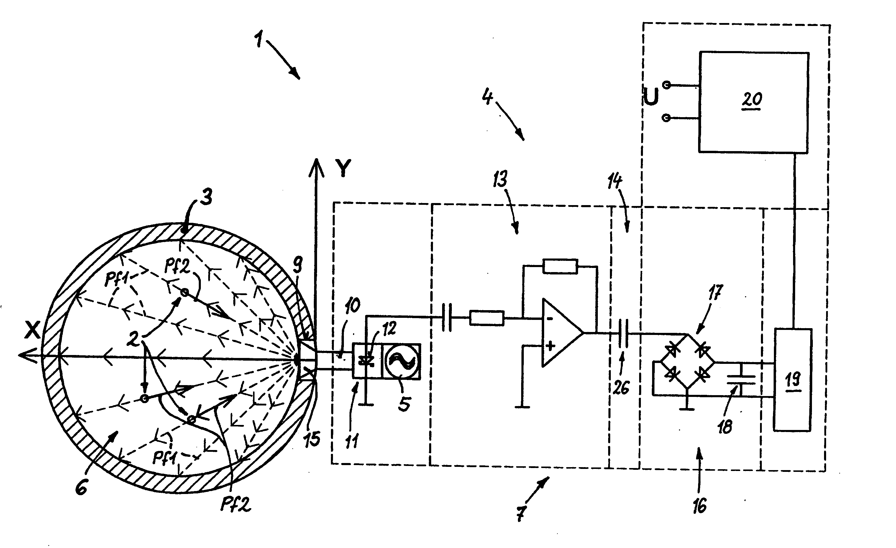
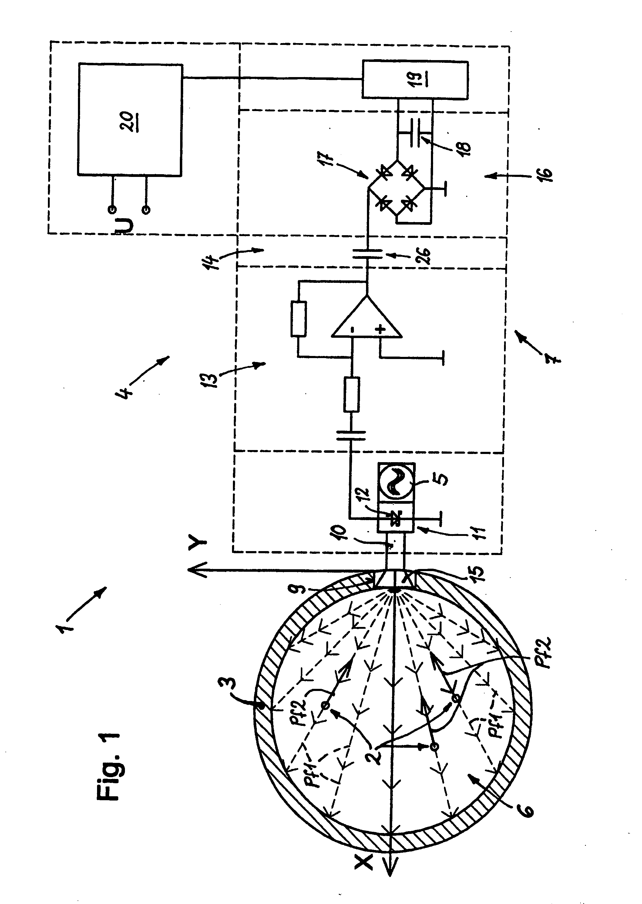
A device 1 shown in FIG. 1 measures the mass flow of a particulate solid 2, which is conveyed using a gas within a flow channel 3. The solid 2 is indicated by a single particle. A measuring device 4 according to the invention is connected laterally to the flow channel 3, and can measure the mass flow or throughput of the solid 2.

The measuring device 4 has a transmitter with an oscillator 5 for producing an electromagnetic field 6 and also a receiver with an evaluation device 7 for measuring the power reflected by the particles of the solid, or the like measure of reflection.

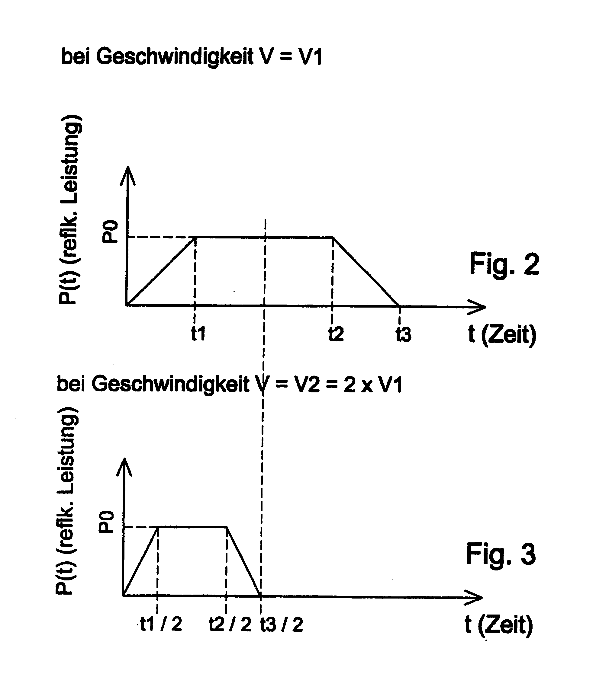
This takes place, as described in more detail herein below, in that the mass flow is formed from the amount of reflection alone. For this purpose, the reflection is measured at least on the solid within the measurement region of the electromagnetic field, from the time course of the measurement signal of the differential quotient of according to time, and the sum formed therefrom.

The measure of reflection ca...


PUM


Abstract

A device used to measure the mass flow of a particulate transported with the aid of a gas. The device includes an arrangement which is used to create an electromagnetic field, with a measuring area being defined therein. An evaluation device for electromagnetic radiation which is reflected at least off of the solid(s) is connected to a detector. The evaluation device is provided with a differentiator which is connected to the detector for detecting reflected electromagnetic radiation. A rectifier is connected to the differentiator in order to determine an amount, whereby mass flow is obtained from the reflection amount. The reflection is measured, at least from the solid(s) within the measuring area of the magnetic field, whereupon the differential quotient is determined as a function of time from the chronological progression of the measuring signal and the amount is obtained therefrom. A measuring signal is obtained from the non-homogeneity of the electromagnetic field, forming the integral over time of the amount of the reflected power per time. The measuring signal is proportional to the mass flow.

Description

BACKGROUND The invention relates to a method for measuring the mass flow of a particulate solid which is transported by means of a gas, a measuring region being defined in an electromagnetic field, and the electromagnetic radiation reflected by the solid(s) being evaluated. Moreover the invention relates to an arrangement for performing the method, which has a device for producing an electromagnetic field in which a measuring region is defined, and with an evaluation device, connected to a detector, for at least the electromagnetic radiation reflected from the solid(s). A series of different methods and devices are known for the determination of the mass flow (also termed “throughput”) of a solid which preferably passed through a tube with a transport gas, for example, air. “Mass flow” will always be understood hereinafter the transport of a weight unit of a material in a given time unit: for example, Kg / s or t / h. The solid is preferably comminuted or milled, so that as a rule it...

Claims


Application Information

Patent Timeline
IPC IPC(8): G01F1/66G01F1/74G01N21/53G01N22/00
CPCG01F1/663G01N22/00G01N21/53G01F1/74
Inventor HAPPEL, JENS
Owner MIC MEASURING IDEAS CONSULTING
Why Eureka
Try Eureka