
Valve train adjustment tool and method

Inactive Publication Date: 2005-06-02
MILLER JAMES M
View PDF3 Cites 3 Cited by
  • Summary
  • Abstract
  • Description
  • Claims
  • Application Information

AI Technical Summary

Benefits of technology

[0010] The instant invention pertains to a device that provides a means for a mechanic of internal combustion engines which utilize rocker arms as part of their operational design, to adjust the operating geometry of the rocker arm's pivot points in relation to the valve stem tip, in a prescribed, predetermined and accurate way, thereby increasing the efficiency of the rocker arm's operational characteristics to the operating geometry sought by the technician who installs the rocker arm to its final operating dimensions.
[0016] On internal combustion engines having valve trains which incorporate rocker arms to open the valves, it is known within the trade that increased operating efficiency and performance can be enhanced by adjustments to the rocker arm's design characteristics, such as the ratio in which it multiplies cam lift to the valve, and also the arching motion which it goes through about its axis in opening the valve, which is determined and measured by a reference line of motion that runs between the tip of the rocker arm's contact surface (for non-roller tip designs), or through the axis of the roller (on roller tip rocker arms), and through the axis about which the rocker arm reciprocates, usually a shaft or fulcrum mounted in any variety of ways to the corresponding component known as the cylinder head. Because the rocker arm is a radial instrument that is converting linear motion on each end, it is obvious to one skilled in the trade that the tangent points for operation are critical to determining the manner of this radial motion. For this reason, an accurate method of establishing the rocker arm's pivot point in relation to the valve tip is critical for a predictable and consistent setting of the rocker arm's orientation with the valve in achieving maximum cam performance. In all cases this requires adjustment of the pivot points for the actual net motion of the valve lift; more accurately quantified by the instant invention as degrees of rocker arm rotation about its axis for whatever linear dimensions the valve lift is expected to operate in.
[0018] The instant invention permits the experienced engine builder to determine the required angle of installation for the rocker arm upon the valve so that the rocker arm's motion can be set to a predetermined valve lift by establishing the position of the rocker arm's pivot point relative to the valve tip from both a closed position of the valve, and a predetermined mid-lift point of valve motion. The instant invention accomplishes this without the use of complicated tools, excessive time in determining the above, or without the user of the instant invention totally understanding more detailed aspects of rocker arm geometry.
[0023] The instant invention provides an adjustment standard for rocker arms not previously known. It permits one who is not necessarily skilled in the trade of precision valve train adjustment to make skilled and precise adjustments by simple measurements which establish a formula used to position the rocker arm and adjust the push rod length for optimum valve train alignment.

Problems solved by technology

Heretofore, there have been no successful attempts at providing a reliable and accurate apparatus and method for calculating the optimum push-rod length.

Method used


Image

  • Valve train adjustment tool and method
  • Valve train adjustment tool and method
  • Valve train adjustment tool and method

Examples


Embodiment Construction

[0036] The example used in the disclosure herein is directed to a 350 cubic inch Chevrolet engine, where the valve lift measurements of 0.500 inch and 0.700 inch are used as reference dimensions. However, the invention can be used for any valve train application. For example, for Ford 302 cubic inch and 351 Windsor engines, the measuring tool 50 is used to perform the methods of this invention but the measurement reference dimensions are 0.522 inch and 0.732 inch.

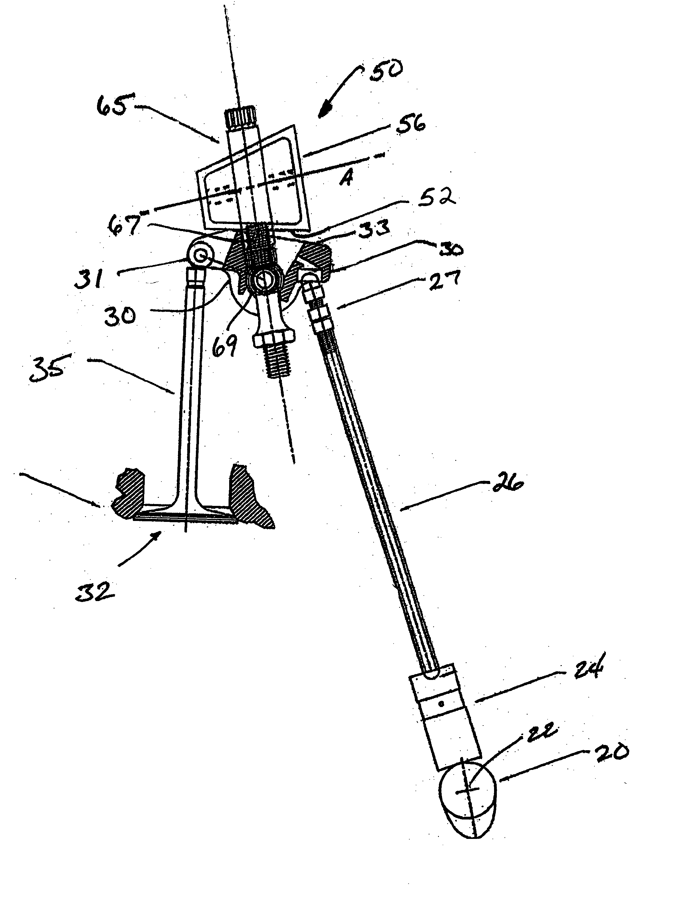
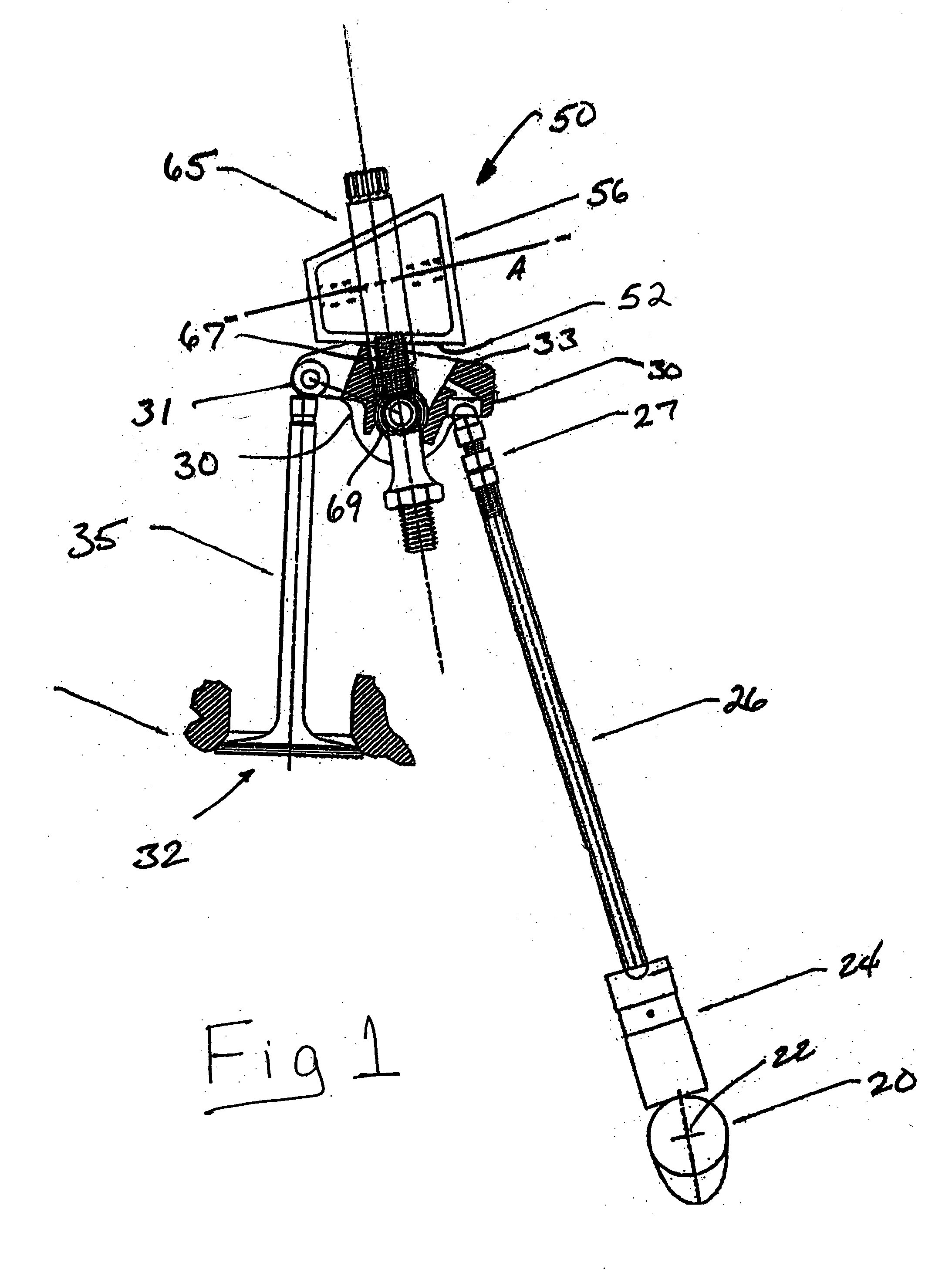
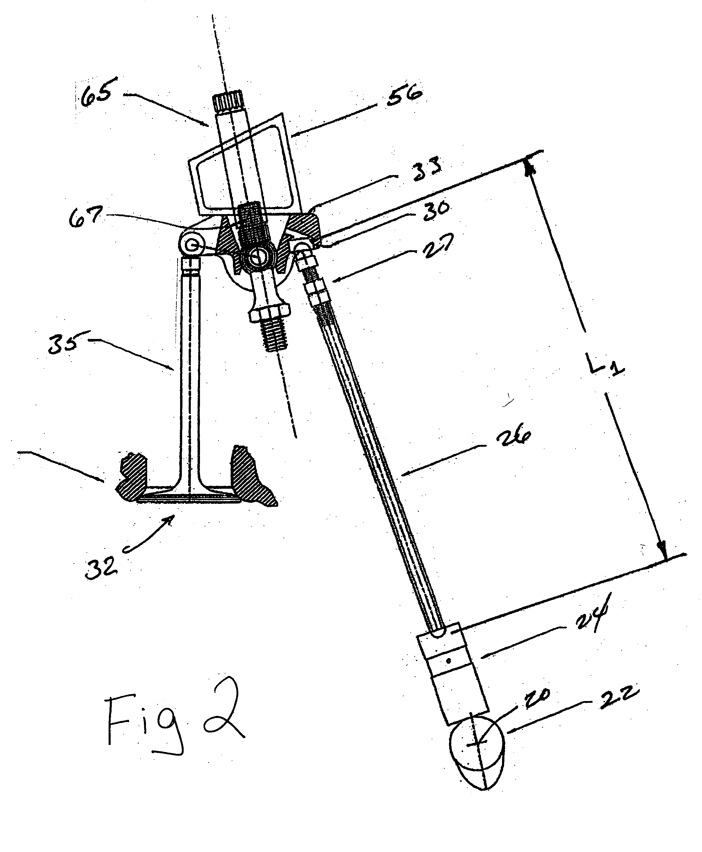
[0037]FIG. 1 shows a typical valve train arrangement employing a cam shaft 20 with a representative cam lobe 22, a cam follower 24, a push-rod 26, a rocker arm 30, and a valve 32.

[0038] The tool 50 can be of any polygonal shape. In the embodiment shown herein, it is four sided, having a first measuring face 52, a second measuring face 54, and first and second end faces 56, 58, respectively. A representative example of the tool 50 of this invention is shown in FIGS. 1-9.

[0039] Tool 50, and the methods set forth herein, no...


PUM


Abstract

A device that provides a means for a mechanic of internal combustion engines which utilize rocker arms as part of their operational design, to adjust the operating geometry of the rocker arm's pivot points in relation to the valve stem tip, in a prescribed, predetermined and accurate way, thereby increasing the efficiency of the rocker arm's operational characteristics to the operating geometry sought by the technician who installs the rocker arm to its final operating dimensions.

Description

CROSS-REFERENCE TO RELATED APPLICATIONS [0001] This application claims priority upon co-pending provisional U.S. patent application Ser. No. 60 / 510,902 under 35 U.S.C. § 119(e).BACKGROUND OF THE INVENTION [0002] Internal combustion engines operate by the controlled burning of an air-fuel mixture ignited by a timed electrical spark or injection of fuel into a sealed cylinder within an engine block which houses a piston. The piston has mechanically compressed this mixture through its reciprocating movement, dictated by a rotating crankshaft attached to the piston through a component known as a connecting rod. This compressed mixture of air and fuel is delivered into the cylinder through passages that control the volume and velocity of this air / fuel mixture, which is ignited by whatever means and immediately generates high, expanding energy from heat from this controlled burning process that forces the piston down, and through the connecting rod this linear motion is converted to circu...

Claims


Application Information

Patent Timeline
IPC IPC(8): B25B27/24G01B5/00G01D21/00
CPCG01B5/0032B25B27/24F01L1/146F01L1/182F01L2800/09F01L2303/01F01L2305/00
Inventor MILLER, JAMES M.
Owner MILLER JAMES M
Learn More