Tool holder block and sleeve retained therein by interference fit

a technology of interference fit and holder block, which is applied in the field of cutting bit holders, can solve the problems of holder block wear, bit wear, and area of holder block that surrounds the bit-receiving hole wear, and achieve the effect of interference fi

Inactive Publication Date: 2006-08-24
SANDVIK INTELLECTUAL PROPERTY AB
View PDF31 Cites 63 Cited by
  • Summary
  • Abstract
  • Description
  • Claims
  • Application Information

AI Technical Summary

Benefits of technology

[0011] Yet another aspect of the invention relates to a hollow sleeve whose shank includes an outer periphery having a radially stepped configuration defined by three surface sections, consisting of front, rear, and intermediate surface sections. Each surface section has a longitudinal length which is substantially equal to one third of a longitudinal distance from the front end of the front surface section to the rear end of the rear surface section. Such relatively long surface sections establish a particularly effective interference fit.

Problems solved by technology

During a cutting operation, not only do the bits tend to wear, but the holder blocks wear as well.
That is, the area of the holder block that surrounds the bit-receiving hole wears due to abrasion thereof by the materials being cut.
It will be appreciated that the need to replace the welded-on holder blocks results in a serious expenditure of time and money.
Instead, the sleeves become worn and are replaced when necessary.
Nevertheless, some sleeves still become prematurely dislodged.
As the sleeve is advanced into the hole, the oil can become trapped and pressurized as the volume of the spaces diminishes, thereby tending to force the sleeve back out of the hole.
Such a reciprocating action of the sleeve can produce undesirable wear of the hole surface.

Method used


Image

  • Tool holder block and sleeve retained therein by interference fit
  • Tool holder block and sleeve retained therein by interference fit
  • Tool holder block and sleeve retained therein by interference fit

Examples


Embodiment Construction

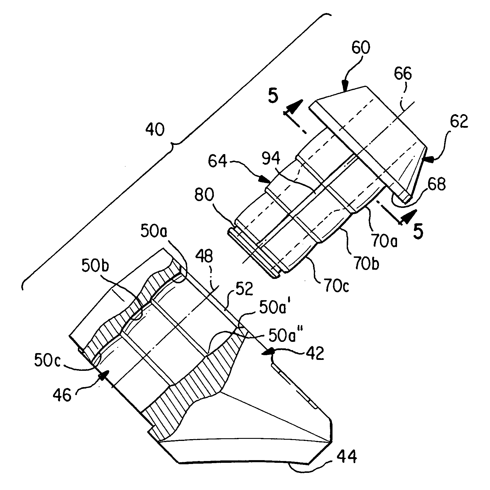
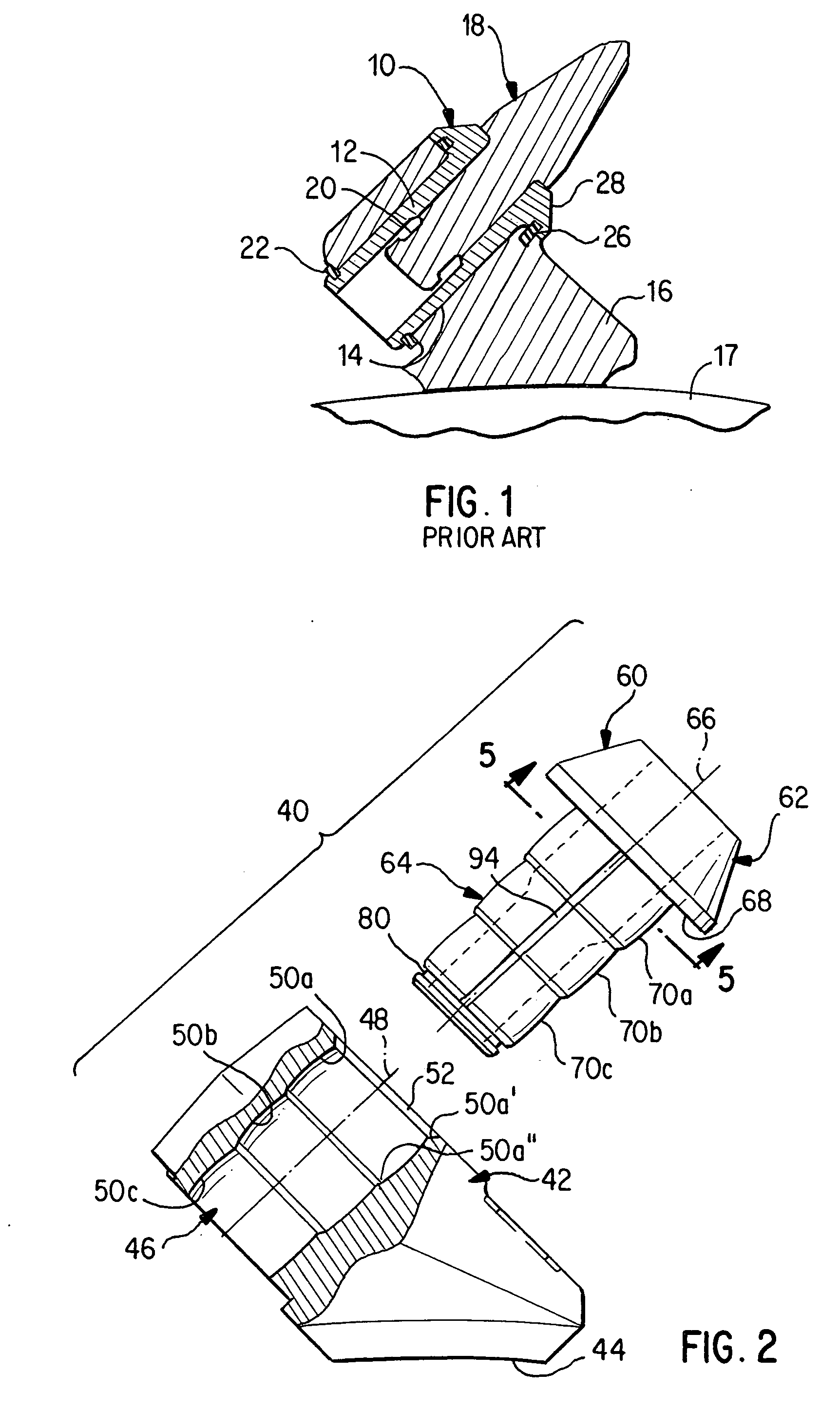
[0021] Depicted in FIGS. 2-5 is a holder assembly adapted to mount a rotary cutter bit on any suitable carrier, such as a rotary drum, an endless chain (e.g., trench digger) or even a non-rotatable carrier. The holder assembly includes a holder block 42 having a curved surface 44 configured for engaging the outer periphery of a rotary drum. The block includes an open ended through-hole 46 which defines a longitudinal center axis 48. The hole 46 includes an inner surface of stepped configuration, wherein the surface includes a plurality of longitudinally adjacent surface sections 50a, 50b, and 50c, which become successively smaller in cross-section in a direction away from a front mouth 52 of the hole 46. Each of the surface sections 50a-c has longitudinally spaced front and rear ends, e.g., see the front and rear ends 50a′, 50a″ of the surface section 50a in FIG. 2, and corresponding front and rear ends 50b′, 50b″, 50c′, 50c″ of the other surface sections 50b, 50c.

[0022] The surfac...


PUM


Abstract

A hollow sleeve is mounted in a hole of a holder block to receive a rotary cutter bit. The sleeve includes a front flange and a shank extending rearwardly from the front flange and defining a longitudinal axis. The shank includes an outer periphery having a radially stepped configuration, wherein an outer surface of the shank includes a plurality of axially adjacent surface sections that become successively smaller in cross-section in a direction away from the flange. Each surface section occupies one-third of the hole length. Each surface section has longitudinally spaced front and rear ends, wherein a portion of each surface section situated between its front and rear ends is spaced farther from the axis than are the front and rear ends. Each surface section has a generally longitudinally extending groove formed therein.

Description

BACKGROUND OF THE INVENTION [0001] The present invention relates to cutting bit holders, especially to holders which support pressed-in replaceable sleeves that carry rotatable cutting bits. [0002] Drum-type cutters are conventional in the mining and road-working industries for example, wherein cutter bits are mounted on a drum which rotates about a horizontal axis. Such cutters can be used to cut through minerals in a mine, or to rip up asphalt or concrete from a roadway. The cutter bits, which are carried by holder blocks welded to the outer surface of the drum, are rotatable about their own longitudinal axes so as to be self-sharpening. During a cutting operation, not only do the bits tend to wear, but the holder blocks wear as well. That is, the area of the holder block that surrounds the bit-receiving hole wears due to abrasion thereof by the materials being cut. It will be appreciated that the need to replace the welded-on holder blocks results in a serious expenditure of time...

Claims


Application Information

Patent Timeline
Patent Type & Authority Applications(United States)
IPC IPC(8): E21C25/10
CPCE21C35/197
Inventor STEHNEY, STEPHEN C.
Owner SANDVIK INTELLECTUAL PROPERTY AB
Why Eureka
Try Eureka